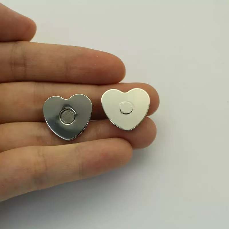
TENS electrode cable strain is an assembly-level design problem. A magnetic interface may limit transmitted tensile load if the assembled connection releases before a vulnerable part is overloaded. This is a design possibility to verify, not a demonstrated cable-protection result for Richarms components in a TENS device.
Magnetic attraction alone does not establish a protective breakaway function. A connection that holds too firmly may transfer a snag load into a cable termination or electrode backing. One that releases too easily may interrupt stimulation during normal movement. For TENS and EMS equipment engineers, the task is to define and verify a useful operating window.
Why TENS electrode cable strain deserves a design review
Die AMG Medical Alevia TENS/EMS instructions warn that removing electrodes by pulling the lead wires may damage the electrodes. TensCare’s lead care guide also advises against pulling leads, loading the lead-to-plug junction or wrapping leads tightly around equipment.
These instructions establish a handling risk. They do not measure how often wires fail, identify one connector type as the cause or demonstrate that magnetic connectors outperform mechanical alternatives.
A practical investigation starts with the failed location: the conductor, solder or crimp termination, connector housing, device socket, electrode tab or supporting film. A pad lifting from skin is another possible outcome, but changing the connector cannot be assumed to solve an adhesive problem.
Follow the load path before changing the connector
When a cable catches on an object, the load travels through the installed assembly. Depending on the design, it may reach the wire termination, mating interface, electrode attachment or device enclosure.
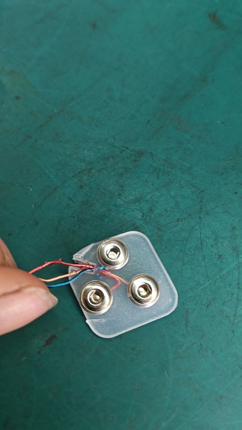
Mechanical stud snaps and pin connections
A stud snap retains its mating part mechanically. A pin connection engages a matching socket. Both can be well designed, and both need suitable cable anchoring and handling instructions. Their release behavior depends on geometry, tolerances, wear and pull direction—not simply on the names “snap” or “pin.”
Magnetic interfaces
A magnetic interface can provide a deliberate separation point. Rosenberger describes breakaway operation as release under a pull on the connector or cable. That is a description of its connector families, not performance evidence for every magnetic contact.
The distinction matters: a detachable contact is not automatically a validated protective device. Check the complete load path, including any path that bypasses the separating interface. Before release, connected parts still carry load; evaluate peak loads and release behavior in the actual assembly rather than inferring protection from connector position alone. A housing lip or guide can also resist lateral motion even when a straight pull separates the faces readily.
For the broader interface comparison, see the magnetic versus snap electrode connector guide.
Breakaway and strain relief perform different jobs
Strain relief supports the cable and limits stress at a termination during bending or pulling. It can involve cable clamps, molded boots, suitable routing or another approved anchoring method. A breakaway interface separates when its release conditions are reached.
A magnetic connection does not replace cable strain relief. Before release, the wire and its anchoring still carry load. After release, the electrical path may be open. A design can therefore need both a controlled separation point and a properly supported cable termination.
There is experimental precedent for this approach in adjacent applications. The research paper Stretch-Safe: Magnetic Connectors for Modular Stretchable Electronics describes controlling magnetic opening force to protect stretchable electrode structures from overstretching. The author institution’s abstract also summarizes this mechanism. Its specimens differ from commercial TENS leads and Richarms snap components; its numerical results should not be transferred to those products.
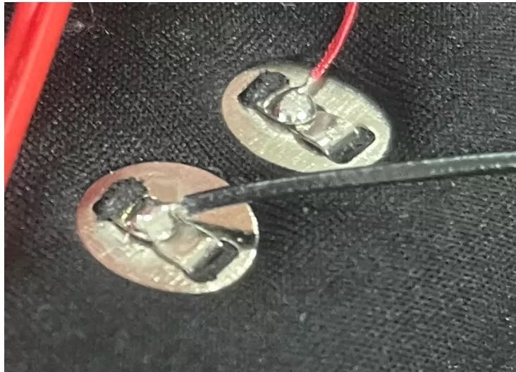
Define the release window for the installed assembly
Start with normal use: cable weight, movement, clothing contact and the intended user action. Then identify which parts must be protected during foreseeable snagging or removal.
The design goal is enough retention for intended operation, with release before unacceptable loading of the protected assembly under the relevant conditions. There is no universal pull-off force suitable for all TENS devices.
Check straight, angled and lateral loads
Measure axial pull-off, angled pull, lateral sliding or shear, and peeling or twisting where relevant. Include cable exit direction, available clearance and any mechanical guidance. A single vertical pull test cannot describe all these conditions.
Check continuity before the parts visibly separate
Contact surfaces can move before complete release. Monitor electrical behavior during movement, rather than assuming that a connection is stable because it still looks attached. Establish an acceptable contact resistance and an interruption detection method with sufficient time resolution for the device requirements.
A static resistance reading alone cannot establish continuous delivery of a stimulation waveform. The device team should assess output behavior with an appropriate load simulator and engineering setup, including partial contact, disconnection and reconnection.
What to test before approving a design
| Question | Suggested evidence |
|---|---|
| Does it stay connected during intended movement? | Installed-assembly movement tests with synchronized force and continuity records |
| Does it release before the protected part is overloaded? | Direction-specific release data compared with allowable loads for the cable, termination, socket and electrode attachment |
| Is the wire securely anchored? | Inspection and pull/bend testing of the actual crimp, solder joint, clamp or molded termination |
| Can the electrode or fabric mounting point withstand handling? | Tests using the intended backing, film, textile, washers and reinforcement |
| What happens when contact is lost or restored? | Device-level assessment of detection, output control and restart behavior using a suitable simulated load |
| Does performance change with use or exposure? | Repeated mating and application-relevant environmental tests, followed by mechanical and electrical checks |
Record the sample revision, both mating parts, fixture, pull speed, direction, cable construction, conditioning and number of samples. Agree acceptance limits before testing. Check variation across samples and after aging; an average release force can conceal individual units that release too early or too late.
Die electrode connector contact reliability guide covers the wider electrical verification process. This article focuses on the relationship between force, release and interruption.
Where Richarms components fit into the review
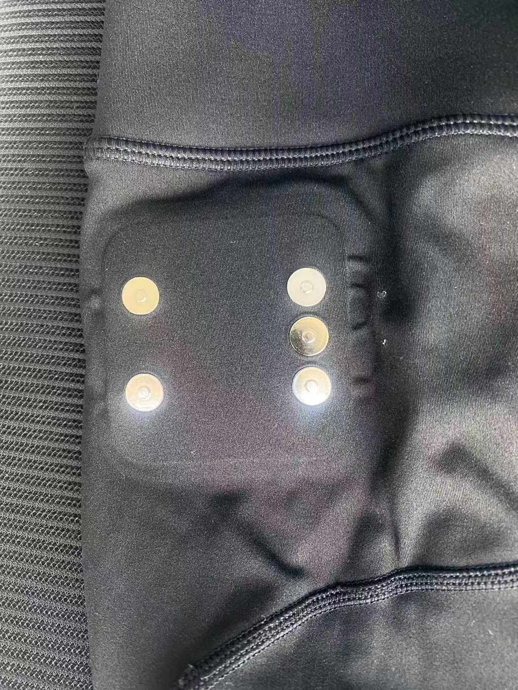
Richarms offers component structures such as the 10mm elektrischer Magnetverschluss und no-prong conductive magnetic snap. These pages are starting points for discussing geometry and integration. They do not establish a tested cable-protection outcome in your device.
Die Richarms conductive snap category lists 8, 10 and 12 mm options. For any candidate, confirm the current drawing, exact mating pair, contact path, rear attachment and supplied assembly scope; a category listing does not establish an approved assembly. Nominal diameter does not specify release force, electrical continuity or compatibility. A custom conductive contact may also be only one part of a larger magnetic assembly.
Use the conductive magnetic snap connector selection guide for the overall specification process. Request model-specific evidence before describing a component as a protective breakaway connector.
Compatibility and safety belong in the design brief
Magnetic self-alignment can assist mating, but it does not guarantee correct orientation, full seating or stable contact. Review polarity and channel assignment, nearby conductive objects, exposed contacts, contamination, unintended mating and interaction with magnet-sensitive equipment where relevant.
An unintended release can interrupt stimulation. The finished device must handle that condition appropriately, including any user indication and reconnection behavior required by its design. The acceptability of interruption depends on the intended application; TENS, EMS and FES should not be treated as interchangeable use cases.
This is a component design discussion, not an instruction to retrofit a patient’s device. Accessory compatibility and finished-device safety require review by the responsible device manufacturer.
FAQ
Will a magnetic connector prevent broken TENS wires?
It may reduce transmitted tensile load if the installed interface releases before a damaging load develops. It cannot prevent every failure, including fatigue or damage occurring elsewhere in the cable.
Is stronger magnetic retention always better?
No. Excessive retention may shift load into a vulnerable joint or mounting point. Insufficient retention may cause unwanted interruptions. Select retention from the application requirements and verify the assembly.
Can it replace a standard snap or pin electrode connector?
Only after checking the complete interface, electrical arrangement, mounting and device requirements. A matching diameter or similar appearance does not demonstrate compatibility.
Does a breakaway connection keep current flowing after release?
A fully separated conductive path is normally open. Partial separation may also affect contact before release. Evaluate both conditions and the device response; do not promise uninterrupted stimulation.
What information should an engineer send Richarms?
Provide the application, mating drawing or sample, cable construction and anchoring, mounting stack, expected movement, desired release behavior, electrical operating conditions, environment, quantity and development timing.
Discuss the interface before selecting a sample
For TENS/EMS device engineers and finished-equipment manufacturers, the useful next step is a defined component brief. Mark the intended separation point and the parts it should protect, then identify which mechanical and electrical requirements already have acceptance criteria.
Contact Richarms to review the component geometry and sample requirements. Keep any cable-strain reduction claim tied to results from the actual assembled design.



 German
 English
 French
 Italian
 Portuguese
 Spanish
 Turkish
 Korean
 Japanese
 Dutch