Conductive magnetic snap selection across 8, 10, 12, 14 and 18 mm platforms, plus custom development. Compare structures, electrical paths and sample validation requirements for your application. Confirm each size and mounting combination before ordering.
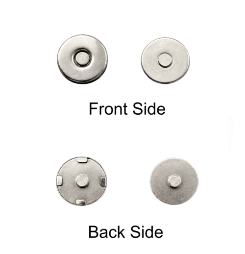
- Tubular rivet, prong, 7-shaped tab, flat tab, dart-shaped and no-prong backs
- Iron, copper and NdFeB magnet; nickel finish, nickel-free plating as a project option
- Sample availability and lead time confirmed for your selected configuration
Request samples View products
Products & Structures

WHAT YOU'LL LEARN
Choose from 8, 10, 12, 14 and 18 mm platforms or custom development. Confirm the exact mounting structure, material and mating geometry for your project. A permanent electrode may not need a magnetic mating pair.
Selection details & validation guidance
Do you need a detachable connection?
For a detachable wearable lead or controller, a magnetic interface may help with repeated connection and removal. A permanent electrode may need neither a mating snap nor a magnet. Confirm this first: it changes the structure, electrical path and test plan.
Textile and flexible assemblies can start with prong or tubular-rivet mounting. Rigid housings and embedded assemblies may call for no-prong, embedded or machined contact concepts. “No-prong” describes the mounting feature; “flat contact” describes the contact geometry. They are not interchangeable specifications.
Platform and mounting selection
| Platform |
Starting point |
What must be confirmed |
| 8 mm |
Existing compact platform |
Structure, rear termination and drawing |
| 10 mm |
Tubular/stem, prong and no-prong options |
Exact assembly and material combination |
| 12 mm |
Available platform |
Available mounting structure and mating parts |
| 14 mm |
Project experience; rivet or prong concepts for evaluation |
Contact geometry and installation envelope |
| 18 mm |
Project experience; prong male component available in SS430 |
Complete assembly, force and rear interface |
| Custom |
Drawing-led evaluation |
Tooling, feasibility and validation scope |
This is a selection starting point, not a catalogue of every available combination. SS430 male components are confirmed for 10 mm tubular/stem, 10 mm prong and 18 mm prong structures. Confirm other materials against the selected drawing.
Specify substrate thickness, reinforcement, hole or slot layout, rear clearance and access for assembly tools. Validate the actual mating pair rather than assuming that parts with the same nominal diameter are compatible.
See all models in the magnetic electrical connector category.
Select materials by their function
A magnetically responsive mating component and a skin-contact electrode may have different requirements. SS430 is a ferritic stainless steel used in the confirmed male-component options above. It should not be treated as interchangeable with a requested 316L electrode.
If a project requests 316L for a nonmagnetic skin-contact electrode, review the geometry, electrical interface and manufacturing requirements first. This is a development assessment, not a claim that every platform is stocked in 316L.
Finish selection must account for soldering, contact behaviour and exposure. Ask for evidence applicable to the selected model and process. A report for one sample or a shared plating process does not certify every finished assembly, establish medical-device suitability or guarantee freedom from skin reactions.
Mounting & Assembly

WHAT YOU'LL LEARN
Map the current path before choosing mounting, soldering or protective coatings. Check substrate thickness, rear clearance and wire strain relief; evaluate the actual assembly on samples.
Selection details & validation guidance
Map the current path before choosing protection
A wired assembly may follow this path:
Device → wire → solder joint → metal contact → mating surface → mating contact → receiving circuit.
A conductive-textile design may instead carry current through textile, a rear metal interface and the snap body. Identify each interface in your drawing. Coating or encapsulating a current-carrying interface can interrupt the intended path even when it improves environmental coverage elsewhere.
For wash-exposed assemblies, review exposed metal, drainage, the rear connection and the textile interface together. Do not treat a protective coating as a complete corrosion solution until the assembled design has been tested.
Rear wiring and soldering
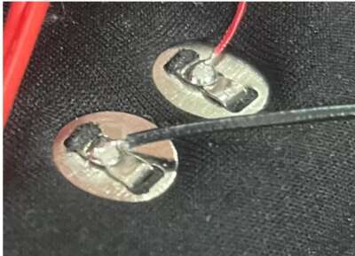
Project assemblies have used solder joints at tubular rivets, prongs and rear metal areas. Richarms can evaluate solderability and tinning with the selected part and wire. Agree on the soldering method, joint location and sample acceptance criteria before production.
Support the wire so that movement is not concentrated at the solder joint. Evaluate the actual joint after installation, including pulling and bending where relevant. Heating can affect the assembly; process settings must be established for the selected components rather than copied from a different snap.
For further detail, see solderable magnetic snap connectors e electrode cable strain relief.
Magnetic or mechanical snap?
| Decision |
Magnetic interface |
Mechanical snap interface |
| Repeated connection |
May reduce mechanical insertion and removal stress |
Requires mechanical engagement and release |
| Retention |
Depends on magnet, area, gap, alignment and mating material |
Depends on engagement geometry and material condition |
| Electrical reliability |
Validate contact path and movement in the assembly |
Validate contact path and movement in the assembly |
| Selection basis |
Actual mating force and application behaviour |
Actual engagement force and application behaviour |
Neither approach is automatically better for every application. Magnetic force is not guaranteed to remain unchanged indefinitely. Compare samples in the same mounting arrangement and environment. Read the magnetic versus snap electrode connector comparison.
Testing & Reliability

WHAT YOU'LL LEARN
Agree project-specific checks for magnetic pull, contact resistance, tinning, wire or joint strength, corrosion exposure and cycling. Relevant available reports can be supplied on request; confirm the selected model and test scope.
Selection details & validation guidance
Build a project-specific validation plan
| Check |
Sample setup and evidence to agree |
| Magnetic pull |
Actual mating material, gap, alignment and vertical pull setup |
| Contact resistance |
Measurement method, contact locations, fixture and project acceptance criteria |
| Tinning and solderability |
Selected finish, wire, joint position and agreed process |
| Wire and joint strength |
Pull direction, restraint, bending conditions and failure definition |
| Corrosion exposure |
Agreed salt-spray conditions and inspection criteria; separate wash or sweat evaluation where required |
| Cycling and wear |
Assembled motion, cycle conditions and electrical/mechanical checks |
Contact-resistance testing is available according to project requirements. We can agree a sample validation scope covering magnetic pull, contact resistance, tinning and solderability, wire or joint strength, corrosion exposure and cycling. Depending on the agreed scope, results can be documented as measurement records, setup photographs, inspection observations and sample feedback. Ask us for available reports relevant to your selected model and finish; report applicability is reviewed for the project. Test limits and sample quantities should be agreed for the application; this guide does not prescribe a universal current rating, resistance, pull force or cycle life.
Review contact reliability e mounting options. Component testing supports development; it does not replace final-device validation.
Applicazioni
WHAT YOU'LL LEARN
Explore detachable wearable leads, conductive textiles exposed to washing and compact sensing electrodes. Each example explains the selection questions and validation path, without claiming unverified test outcomes.
Selection details & validation guidance
Three project situations
Detachable wearable stimulation lead
The engineering questions include retention, solder-joint loading, corrosion exposure and repeated mating. Start with the intended connection and cable routing, then compare sample assemblies. This is a validation workflow, not a claim of clinical performance.
Conductive glove exposed to washing
A project reported rust in a previous supplier’s assembly. Covering the rear metal interface could also obstruct the textile-to-snap current path. The useful first step is to map that path and define the wash conditions before evaluating protection. No completed corrosion remedy is claimed here.
Compact multi-contact sensing electrode
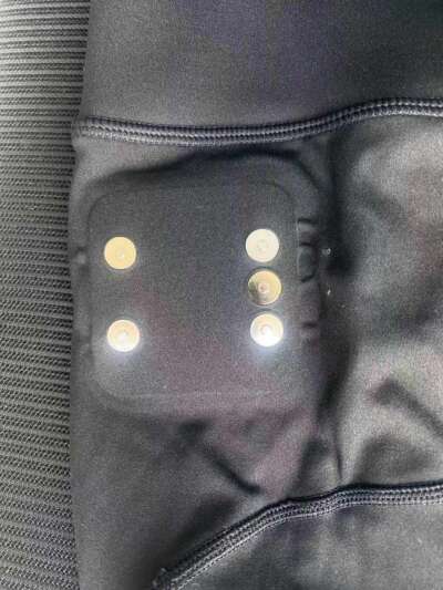
An early concept requested several contacts within a compact space, a smooth surface and a particular stainless-steel grade. The first decision is whether the electrode should be permanent or detachable. Existing 14 mm rivet or prong concepts can inform an initial review; a flat female capsule without a centre hole or a machined flat male contact may require development. Material selection follows that structural review.
Custom Development

WHAT YOU'LL LEARN
Start with an existing platform where suitable. Confirm whether you need a single contact, a mating pair or an assembled unit, then agree the drawing, materials, finish and sample validation scope.
Selection details & validation guidance
From brief to samples
State whether you need a single contact, a mating pair or an assembled unit. This determines the drawing and quotation scope. For skin-contact applications, a nickel-free plating option does not mean every material in the complete part is nickel-free; confirm the selected construction and evidence.
Send your drawing or assembly sketch with the electrical path marked. Richarms can then review a suitable platform, mounting method and rear connection. Confirm the sample drawing, materials, finish and agreed checks before placing the sample order.
Use sample feedback to settle the design and acceptance criteria before discussing production. Availability, quantities and lead times depend on the confirmed configuration. See custom conductive magnetic snap development.
Frequently asked questions
Does every diameter offer every mounting structure?
No. The available platforms are 8, 10, 12, 14 and 18 mm, but each size and structure combination needs confirmation against a drawing.
Can I choose a replacement by diameter alone?
No. Check the mating geometry, gap, retention, mounting and electrical interfaces. Equal nominal diameters do not establish compatibility.
Can a wire be soldered directly to the snap?
Some assemblies use tubular rivets, prongs or rear metal areas as solder locations. Evaluate the selected part, finish, wire and process together, including strain relief.
Does a permanent electrode need a magnetic mating pair?
Not necessarily. A permanent electrode may use a direct electrical connection without a detachable snap or magnet.
Can a coating protect a washable textile connection?
Protection must preserve the intended electrical path. Define the wash conditions and evaluate the complete assembly before accepting a coating approach.
Is one nickel-release report valid for all configurations?
No. Confirm the report’s sample, method, date and relationship to the selected configuration. Sharing a plating process does not mean every product was tested.
At a glance
| Sizes |
8, 10, 12, 14 and 18 mm platforms plus custom development. Exact dimensions, tolerances and mounting combinations require the selected drawing. |
| Materials |
Materials depend on the selected structure. SS430 male components are confirmed for 10 mm tubular/stem, 10 mm prong and 18 mm prong. Other materials require drawing review. |
| Finish |
Nickel. Nickel-free plating available as a project option for selected models — this does not mean the whole part is nickel-free; tell us your nickel requirement and test method. |
| Electrical |
Validated against your application on samples; send your current, voltage and contact-resistance targets. |
| Samples |
Sample configuration and validation scope agreed for your project |
| MOQ |
Confirm quantities for the selected configuration |
| Lead time |
Confirm availability and lead time after drawing and sample-scope review |
Send your project details
Please include in your message:
- Application / device type
- Size and rear structure you are considering, or your drawing
- Mounting method: riveted, prongs, soldered tab or embedded
- Operating current and voltage; contact-resistance requirement if any
- Finish or nickel requirement
- Estimated annual quantity and target sample date
Email info@richarms.com · WhatsApp +86 15820655200
Need a few pieces for a prototype? Standard items are available in small quantities from our online stock store.


 Italian
 English
 French
 Portuguese
 Spanish
 Turkish
 Korean
 Japanese
 German
 Dutch