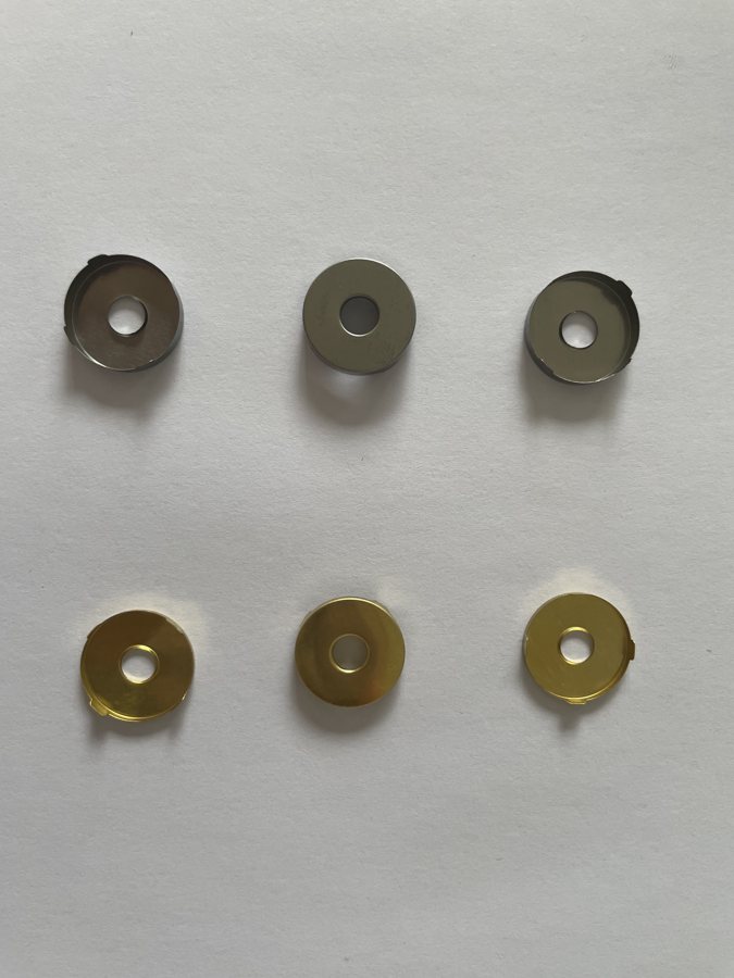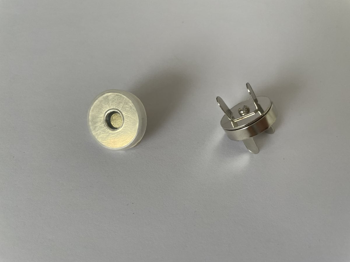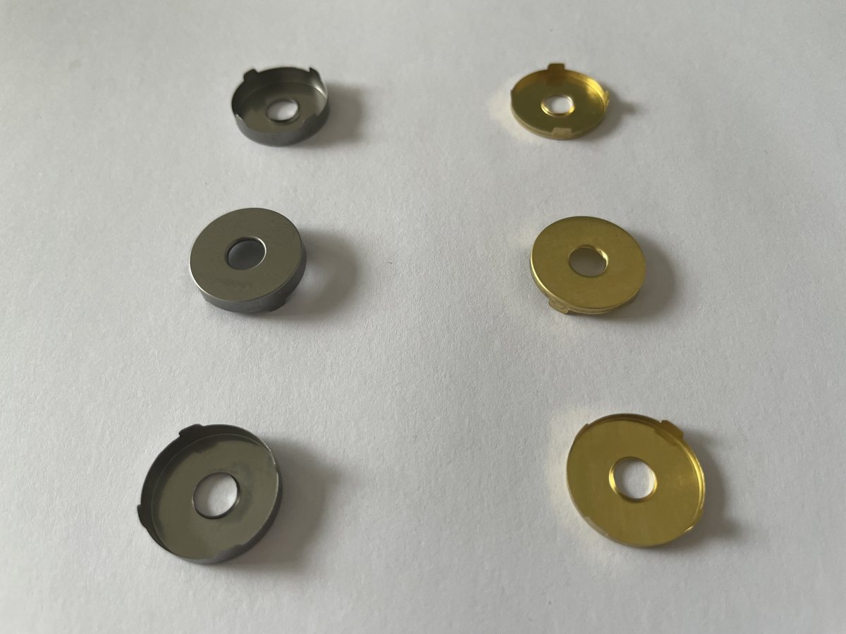
Conductive magnetic snap connectors combine a detachable contact interface with magnetic attraction. For a device developer, selecting one is a mechanical and electrical integration decision: the mating parts, mounting structure, contact path and assembly process must work together in the finished design.
This guide is for engineering and purchasing teams evaluating electrode connections for TENS and EMS projects. Use it to prepare a sample specification, compare available structures and identify the evidence needed before production. Browse the Richarms electrical connector category for existing component formats.
What conductive magnetic snap connectors do
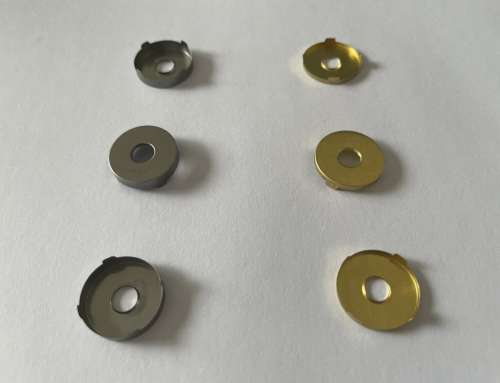
The magnetic arrangement helps bring the mating parts together and contributes to retention. Electrical contact depends on the actual conductive surfaces and how they meet. These functions should be identified separately on a drawing; a metal cap, magnet, contact insert and terminal need not all perform the same role.
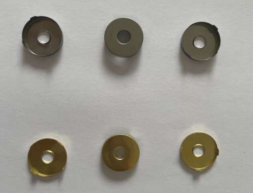
A clasp intended only to fasten fabric is not an electrical connector specification. Likewise, a conductive metal contact supplied for a custom assembly does not, by itself, establish that the complete assembly includes a magnet. Ask the supplier to identify the supplied parts and mark the intended current path.
Define the device interface before choosing a part
TENS refers to transcutaneous electrical nerve stimulation; the NHS overview describes its use for temporary pain relief. EMS refers to electrical muscle stimulation. Those application labels do not specify a connector footprint, contact arrangement or interchangeable accessory.
Treat functional electrical stimulation, or FES, as a separate application brief when relevant to the project. An electrode connection used in one device cannot be assigned to another application simply because both use electrical stimulation. The device team should define the intended function, output conditions and accessory interface.
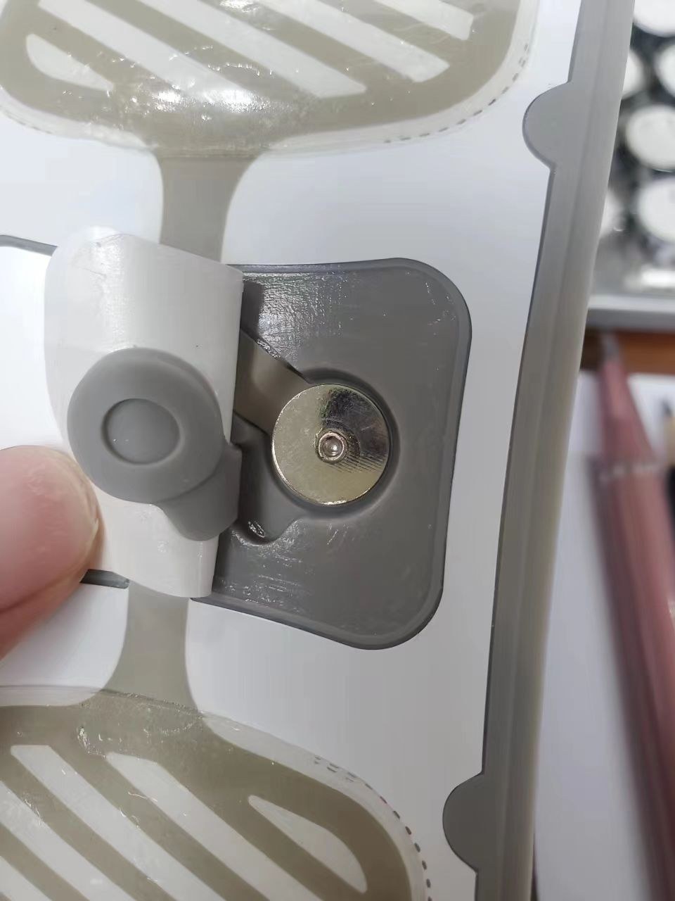
Document which side belongs to the cable, electrode, enclosure or board. Identify every conductor and whether rotation could change alignment. Record what is replaced by the user and what stays permanently assembled. Connector selection does not establish the finished device's clinical suitability or regulatory status.
Compare the complete mating pair
Start with the counterpart, not a nominal diameter. A magnetic pair, a mechanically retained stud snap and a pin-and-socket connection can have different engagement profiles and release actions. Names used in listings are not sufficient evidence of compatibility.
Use the magnetic versus snap electrode connector comparison to decide which interface drawings and samples to request. Check the contact area, seating depth, usable clearance and intended orientation. Include both mating halves in the sample review even if only one side is being purchased.
Choose a mounting structure around the assembly
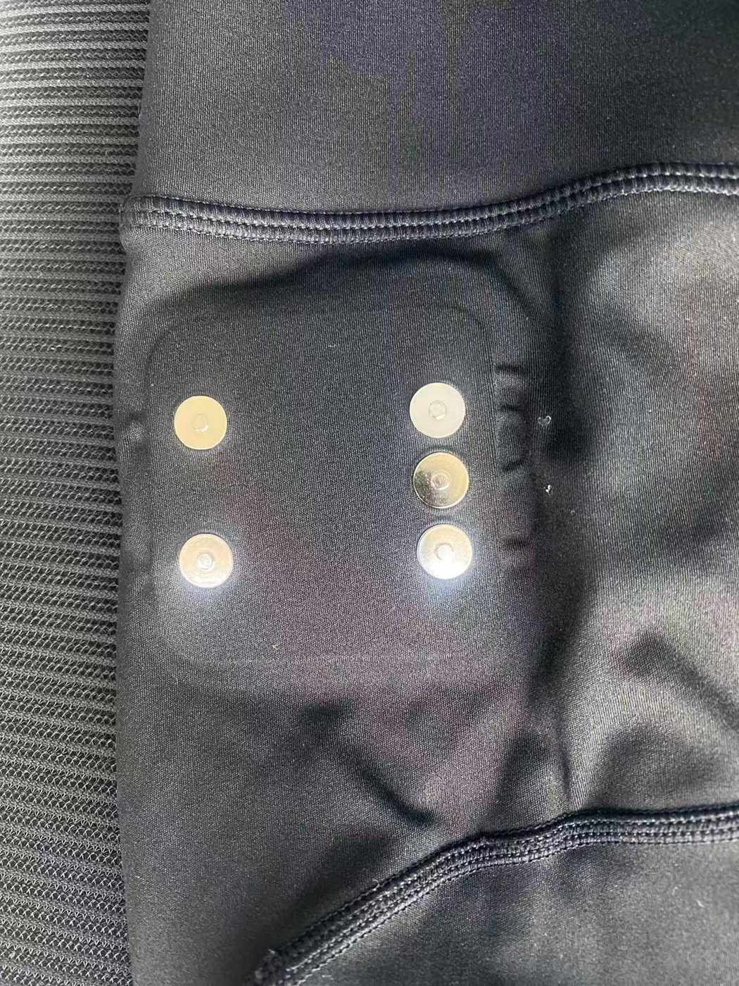
The rear attachment can affect board layout, enclosure clearance and the path by which external loads reach the joint. A stem, flat prong, angled terminal or no-prong back presents a different integration problem.
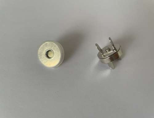
For example, Richarms lists an electric magnetic snap with a flat-prong structure そして no-prong conductive magnetic snap. These are starting points for structural comparison, not confirmation of suitability for a particular medical device or assembly process. Request the current controlled drawing for the selected model.
について electrode magnetic snap mounting guide explains which dimensions to capture. Evaluate the installed assembly with its washers, insulation, housing and wire routing, rather than approving only the loose component.
Separate solderability from magnetic performance
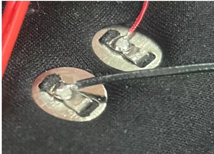
A solderable terminal does not prove that the complete magnetic assembly will tolerate the proposed soldering cycle. Confirm where heat is applied, which components are already fitted and whether the process involves pre-tinning, a single joint or rework.
Prepare a process review using the solderable magnetic snap connector guide. Agree on the information to record and the checks needed after assembly. Do not transfer an unverified temperature or dwell-time claim from another connector design.
Specify the evidence needed for approval
A useful sample plan links each requirement to a method and a decision. For example:
- Dimensional fit: inspect the mating geometry and installed clearance against the agreed drawing.
- Electrical contact: define the measurement boundary, instrument conditions and acceptable result.
- Retention and release: identify the pull direction, fixture and operating action being evaluated.
- Assembly: record the actual materials, fastening or soldering process and inspection criteria.
- Exposure and repeated use: define the relevant conditions and the checks before and after them.
Keep the test results tied to a sample revision and lot. The electrode connector contact reliability guide covers how to separate connector-level observations from cable, electrode and device effects. A short demonstration should not be described as a lifetime result.
When a custom component makes sense
A standard pair may be worth evaluating first if its interface and rear mounting fit the design. A custom contact becomes relevant when a specific dimension, terminal position, housing interface or finish cannot be accommodated by an existing option.
について custom conductive magnetic snap development guide sets out a drawing-to-sample workflow. Decide whether the request covers a single contact part, a mating pair or a larger assembled unit; each requires a different quotation and approval scope.
Related Reading
Send a focused sample brief
To discuss a project with Richarms, provide the application, counterpart drawing or sample, mounting space, proposed assembly method, use environment, expected quantity and timing. State which requirements are confirmed and which are still being developed.
Contact Richarms for a component review. A defined interface and a sample validation plan give both teams a practical basis for deciding what to supply and what still needs testing.


 Japanese
 English
 French
 Italian
 Portuguese
 Spanish
 Turkish
 Korean
 German
 Dutch