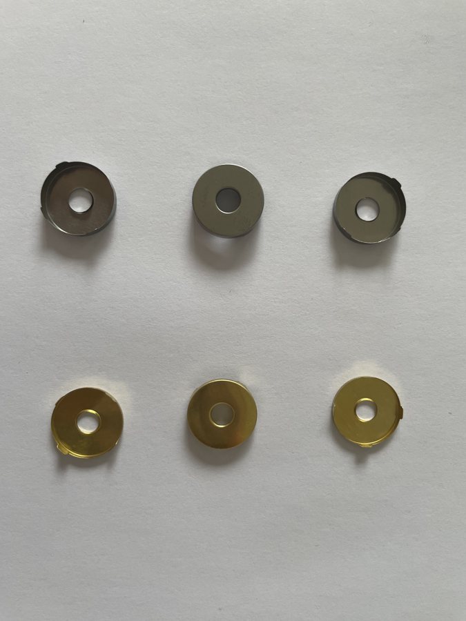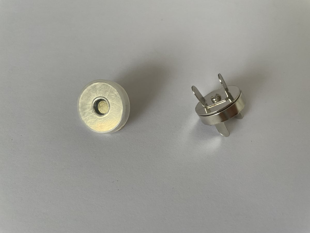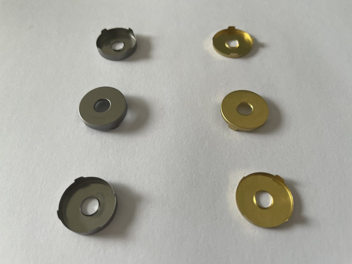
The magnetic vs snap electrode connector decision is about how two parts align, retain and conduct in the intended assembly. It cannot be resolved by comparing only the visible diameter or selecting the part with the strongest pull.
Terminology needs care: a magnetic connector may itself be sold as a “magnetic snap.” In this comparison, “stud snap” means a mechanically retained snap interface, while “magnetic” refers to a mating interface that uses magnetic attraction. Confirm the actual structure behind each supplier's product name.
Magnetic vs snap electrode connector: compare the interface
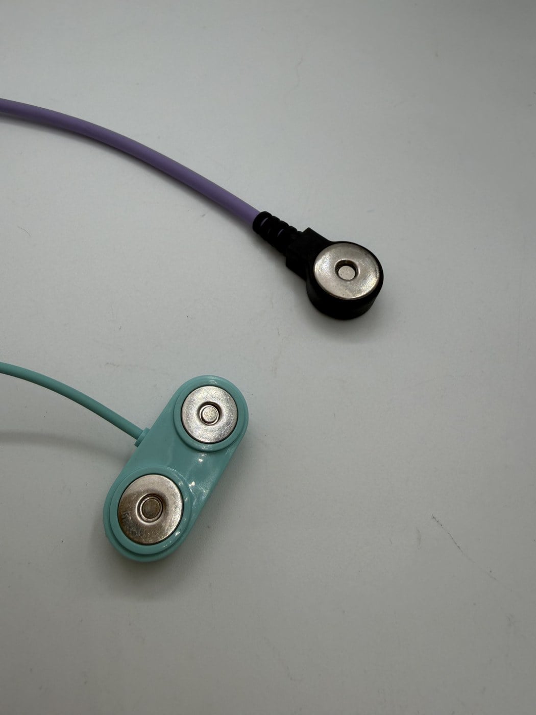
A magnetic pair can help draw compatible mating surfaces together. A stud snap relies on the engagement of its mating mechanical features. A pin interface places a conductor into a matching socket or receiving feature. Each still needs a defined contact path and a suitable attachment to the cable, electrode or device.
Ask for the cross-section and mating instructions. Some magnetic designs also include guidance or mechanical retention, and some interfaces allow movement that others restrict. Do not assume that a product label describes every feature of the supplied part.
For the wider selection process, use the conductive magnetic snap connector guide.
Use a comparison sheet that captures the differences
| Selection question | Magnetic pair | Mechanical stud snap | Pin interface |
|---|---|---|---|
| How do parts engage? | Bring the specified mating faces together; check orientation | Engage the defined stud and retaining feature | Insert the specified pin into its matching socket |
| What establishes compatibility? | Face geometry, contact layout and magnetic arrangement | Mating dimensions, profile and retention geometry | Pin dimensions, socket geometry and insertion depth |
| What should be tested? | Contact seating, retention and release in the assembly | Engagement, release and stability of the attachment | Seating, retention and the effect of cable movement |
| Is matching nominal size enough? | No | No | No |
This comparison describes questions to investigate, not a ranking of performance. The useful result is a matched interface that works within the project's requirements.
Check more than the nominal size
Mark the contact surface, available seating depth, insulating features and surrounding clearance. Include tolerances for both halves. If a cable head or electrode backing restricts access, check the operator's approach and release movement using the complete sample.
A part may appear to fit while touching only at an unintended edge. Another may engage but place excessive load on the supporting film, board or housing. Neither issue can be resolved from a front-view photograph alone.
Use the mounting and size checklist before requesting a substitution. When the counterpart is proprietary or incompletely documented, ask the device or accessory owner to confirm the permitted interface rather than treating a look-alike as a replacement.

Separate connector problems from electrode problems
A connection complaint can originate at the mating contact, cable termination, electrode backing or another part of the system. Poor adhesion to skin and an intermittent metal connection require different investigations.
Begin with a documented observation: what moved, what became disconnected and under which conditions? Keep electrical tests within an appropriate engineering setup; this comparison is not an instruction to modify or trial a stimulation device on a person.
O contact reliability testing guide explains how to define the test boundary and record movement-related interruptions. A subjective change in stimulation sensation does not establish which component caused it.
Compare sourcing scope as well as geometry
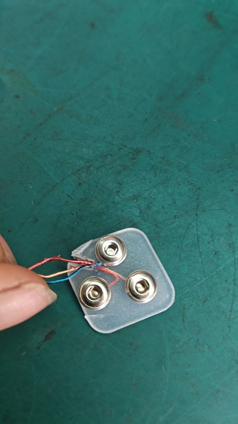
Confirm whether the quote includes one contact, a complete pair, washers or a terminated lead. Request the assembly drawing and identify any parts to be supplied by another manufacturer. Otherwise, apparently similar quotations may cover different deliverables.
Richarms' electrical connector category provides component formats to discuss. Send the counterpart drawing and installation details to review a proposed match. Keep final approval tied to the agreed samples and intended assembly, not to a claim that one connector family is universally better.


 Portuguese
 English
 French
 Italian
 Spanish
 Turkish
 Korean
 Japanese
 German
 Dutch