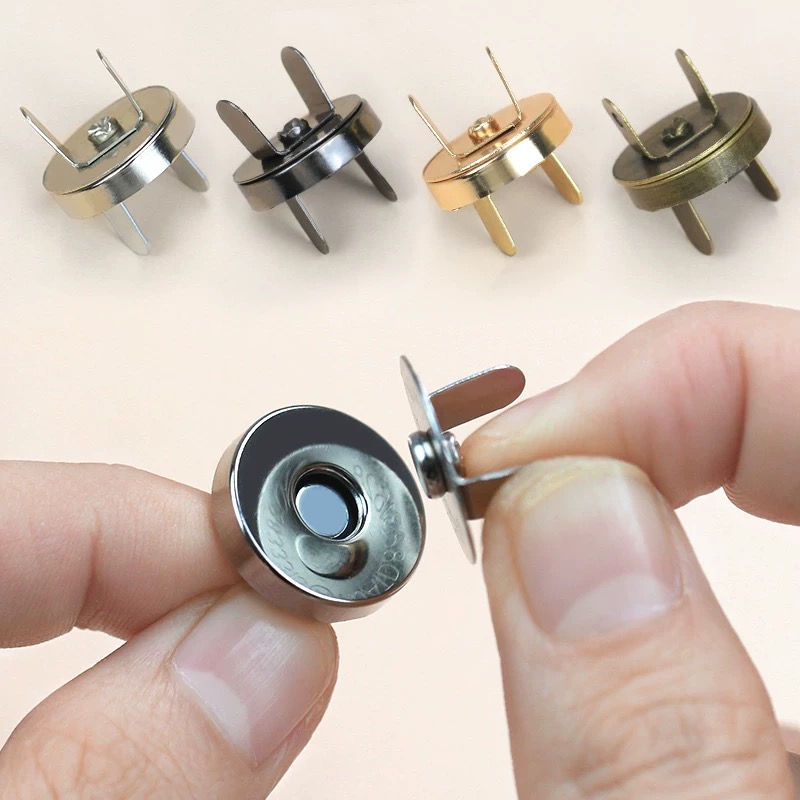
A solderable magnetic snap connector needs two separate reviews: whether the intended terminal can form the required solder joint, and whether the complete assembly retains its required properties after that process. A terminal that accepts solder does not establish a safe process window for every nearby material or magnetic component.
This guide helps engineering teams prepare a process brief and sample comparison. It does not prescribe a universal soldering temperature, contact time or reflow profile.
Identify the solderable magnetic snap connector structure
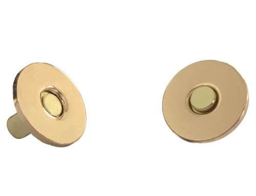
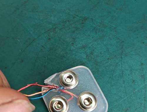
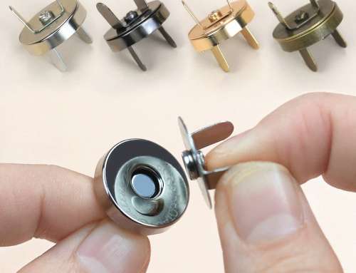
Mark the terminal or surface intended for soldering on the drawing. Identify the substrate, surface finish, magnet location, insulating parts and any bonded or enclosed features. Clarify whether the delivered item is a complete assembly or a contact part that receives the magnetic component later.
A listing described as “no prong” does not necessarily provide an approved soldering surface. Similarly, a mounting tab should not automatically be treated as an electrical terminal. Request instructions for the actual part and discuss the complete connector selection brief.
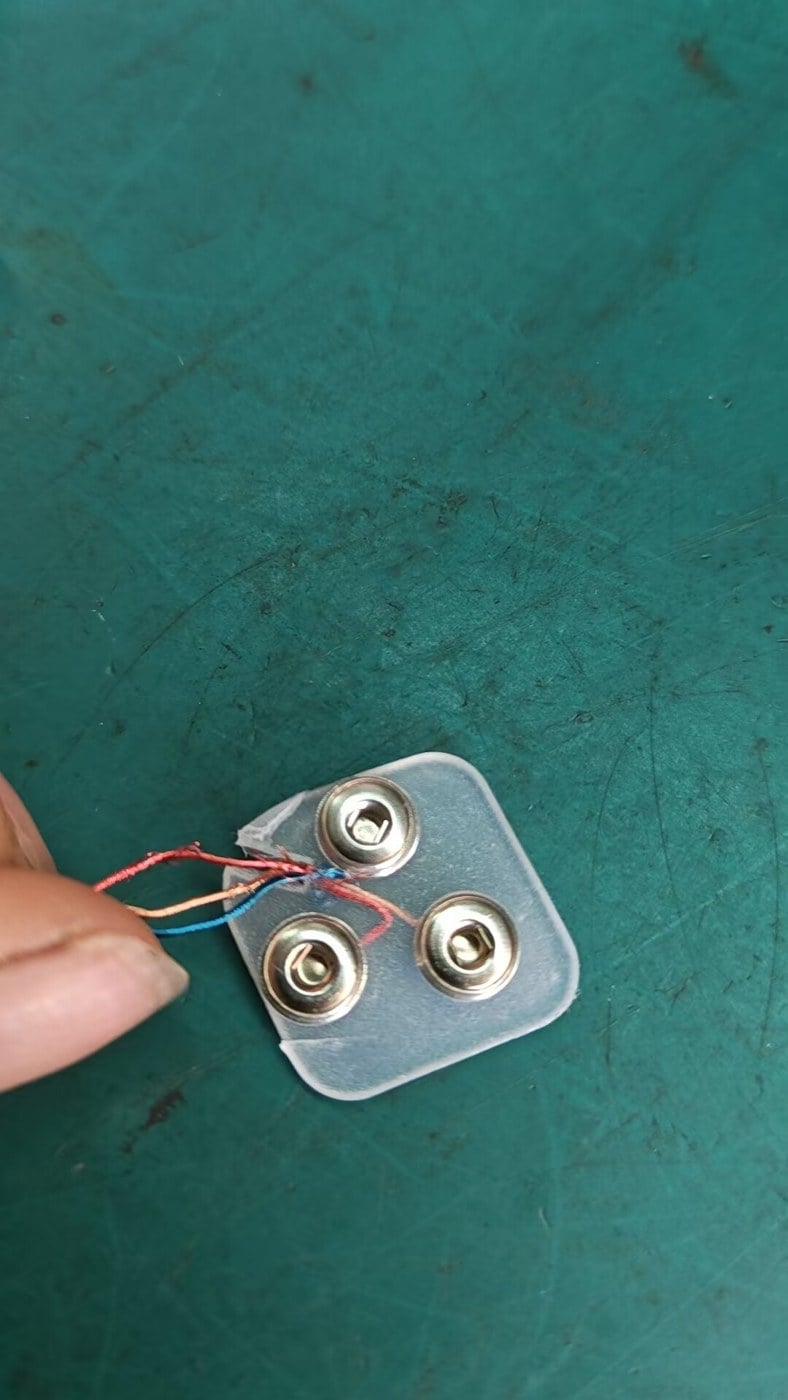
Keep heat away from unqualified magnetic parts
K&J Magnetics advises against soldering directly to its neodymium magnets because of heat-related damage and associated risks. That guidance concerns the magnet itself; it is not a qualification of a terminal elsewhere in a connector assembly. See the manufacturer's magnet FAQ.
For a proposed terminal-soldering operation, determine how heat reaches the rest of the assembly. Magnet material and grade alone do not establish the allowable process for the finished component. Geometry, assembly sequence and the actual thermal exposure also need review.
Ask whether attaching the wire or board before fitting heat-sensitive parts is an available manufacturing option. Treat this as a feasibility question, not as an instruction to disassemble a supplied connector.
Give the supplier a reproducible process brief
Include the following with the selected model and drawing revision:
- The joint location, terminal geometry and board or wire details.
- Solder alloy, flux and proposed cleaning process.
- Equipment type, setpoint and the method used to assess actual joint or component temperature.
- Pre-tinning, heating duration, cooling and any repeated heating or rework.
- Fixture contact, support and nearby heat-sensitive materials.
- The inspection and electrical requirements for the finished assembly.
Distinguish an equipment setpoint from a measured component temperature. Record how the sample was processed so an apparently successful joint can be reproduced and compared with a later trial.
Plan before-and-after checks
Use identified samples and retain a record of their initial condition. After the proposed process, inspect the joint, plating, enclosure, seating and alignment. Compare the relevant electrical and mechanical results using the same setup and test boundary.
For retention measurements, document direction, separation speed, mating part and fixture. For resistance measurements, document the sensing points and instrument conditions. These records help avoid attributing a changed reading to heat when the measurement arrangement has also changed.
O electrode connector contact reliability guide provides a framework for the electrical checks. Acceptance limits should come from the approved project requirements; a single before-and-after measurement is not a general product rating.
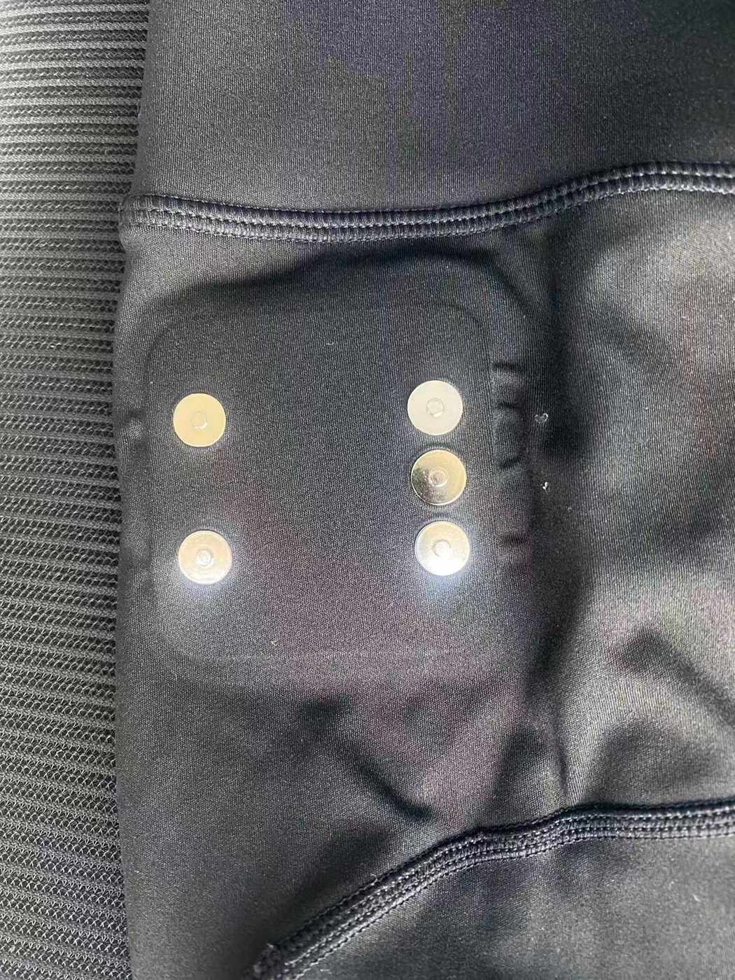
Include the mounting method in the review
A component may form a suitable joint yet sit incorrectly in the housing or transfer cable movement into that joint. Check how the assembly supports the connector and provides strain relief. Review access for inspection and any realistic rework operation.
Compare the layout against the mounting guide. Richarms lists a flat-prong electric magnetic snap that can be discussed as a structural option. Confirm the current drawing and process requirements for the selected version rather than adopting an unverified soldering claim from a listing.
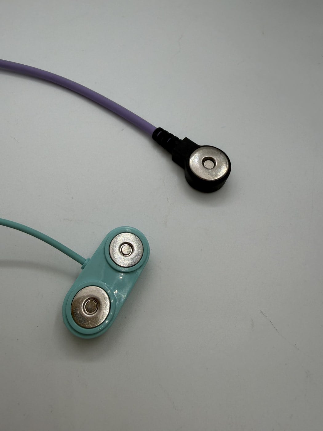
Move from a trial to a controlled instruction
If the samples meet the agreed criteria, record the approved component revision, materials, equipment settings, process checks and inspection method. Define how changes in the terminal, finish or assembly sequence will be reviewed.
Send Richarms your drawing and proposed soldering conditions for a component discussion. Where a standard structure cannot accommodate the process, the custom development guide explains how to define the change and its sample approval scope.


 Portuguese
 English
 French
 Italian
 Spanish
 Turkish
 Korean
 Japanese
 German
 Dutch