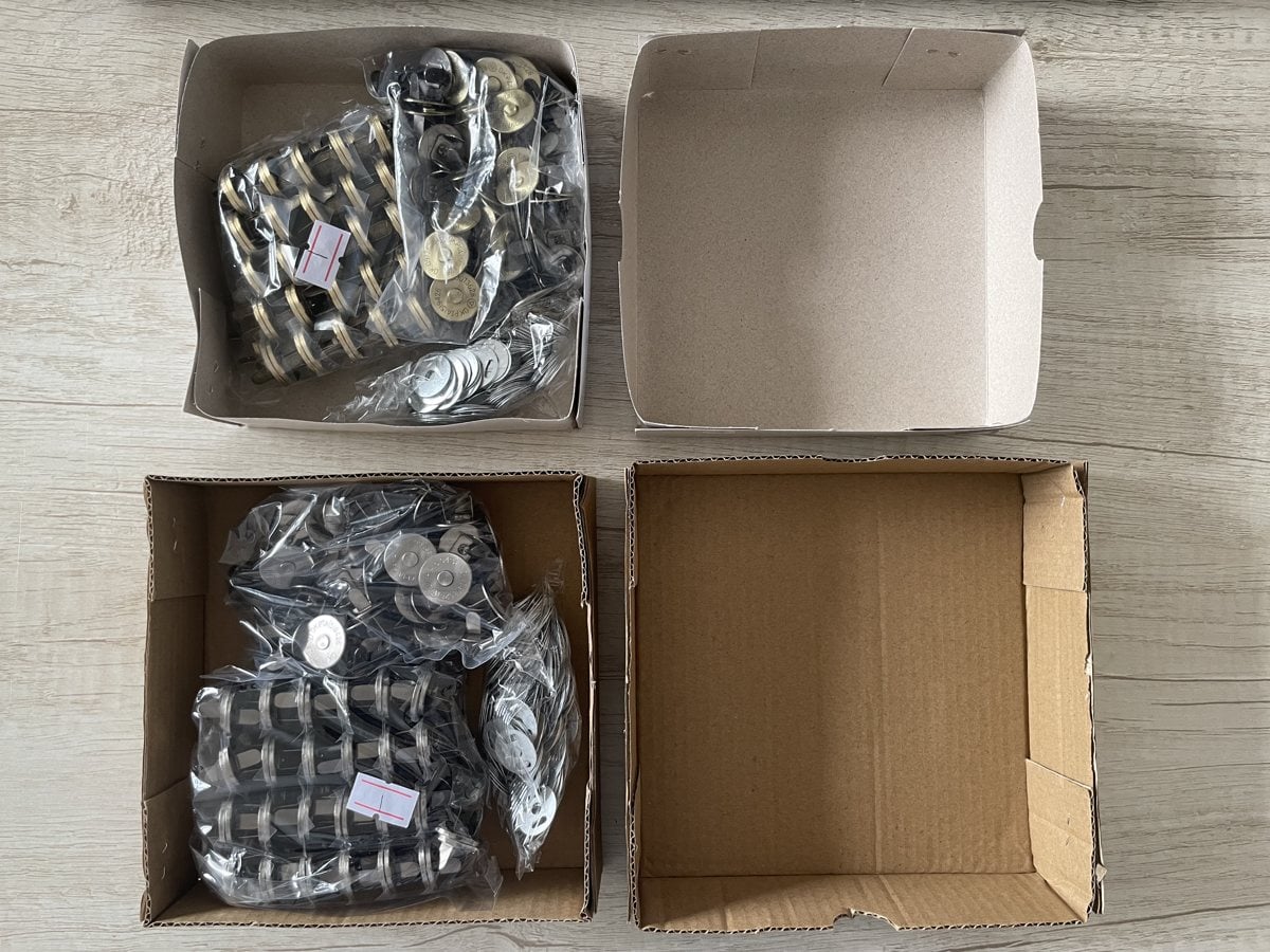
A no-prong conductive magnetic snap is first of all a mounting decision. The back is flat, with no protruding prongs or rivets, and the part is intended to be embedded rather than pierced through a panel. That can be the right starting point for a rigid housing or an injection-moulded assembly. It is not, by itself, a complete electrical or mating-pair specification.
The published conductive magnetic snap no prong is described as a prongless, flat-back fastener for integrated injection-moulding applications. The conductive magnetic snap selection and validation guide adds a distinction that should be kept in the brief: “no-prong” describes the mounting feature; “flat contact” describes the contact geometry. They are not interchangeable specifications. This article stays with mounting, sampling and validation. It does not assign current, voltage, resistance or cycle-life ratings, and it does not treat the product as a medical-device or electrode tutorial.
What the no-prong mounting feature is
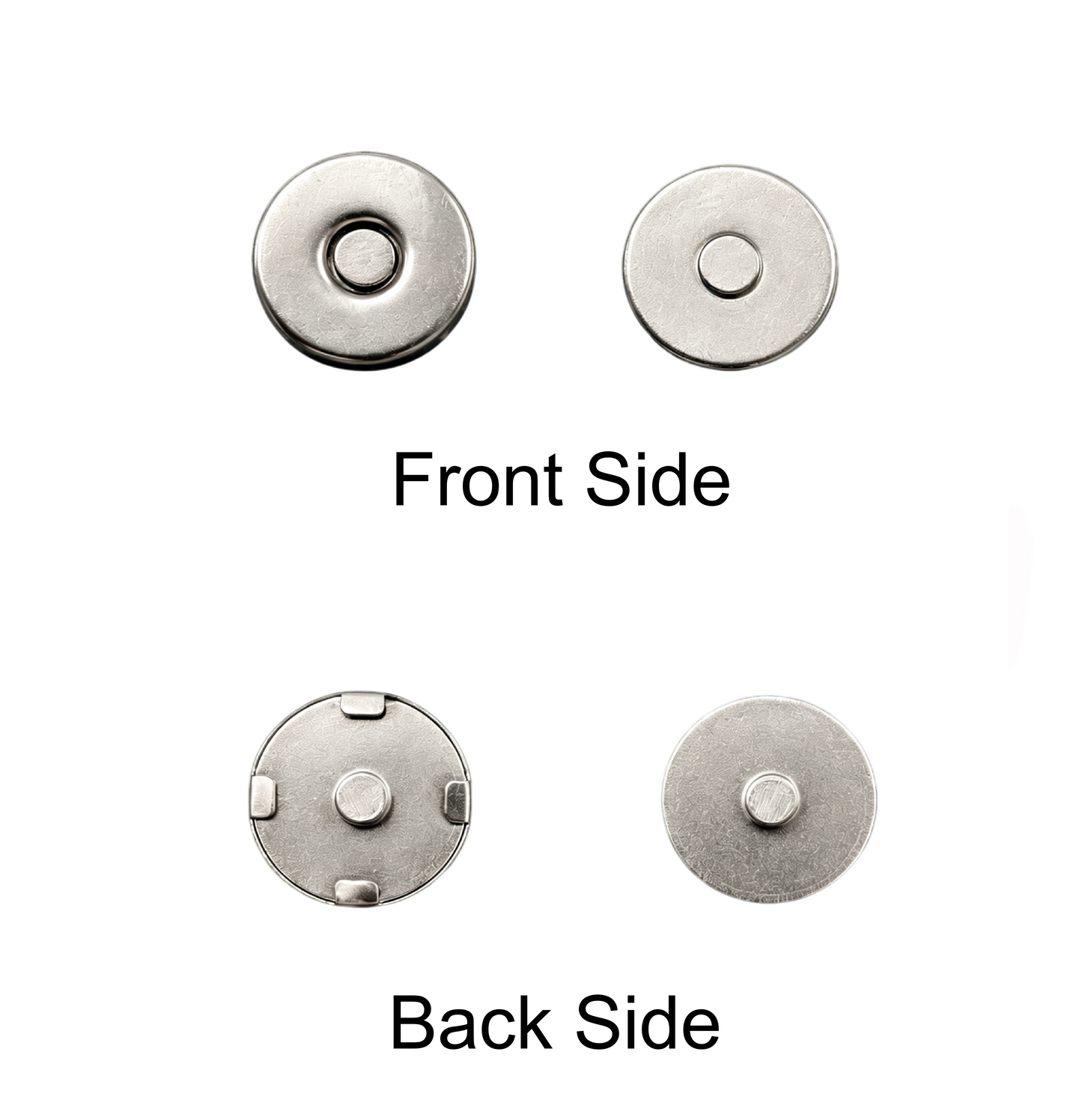
The product page describes a flat, prong-less back with no raised pins, intended for embedded, hidden installation and for thin-wall plastic products. The comparison it publishes is practical: the no-prong design is presented for embedded full-wrap injection moulding, while traditional pronged snaps are described as fitting surface mounting and as needing avoidance grooves in the mould. The no-prong version is described as working with a simpler flat mould structure. Those are published construction points to evaluate on the actual housing and tool, not an assurance of mould performance.
Main materials are described as a metal substrate, a conductive electrode sheet and an NdFeB magnetic core. Surface treatments listed include nickel plating, gold plating and a custom anti-oxidation coating. Standard sizes are described as being in stock, with non-standard sizes available on request. One displayed configuration on the product page gives a thickness of 2 mm and a female diameter of 10 mm. That is a displayed example. Exact dimensions, tolerances and the mating geometry should be taken from the selected drawing.
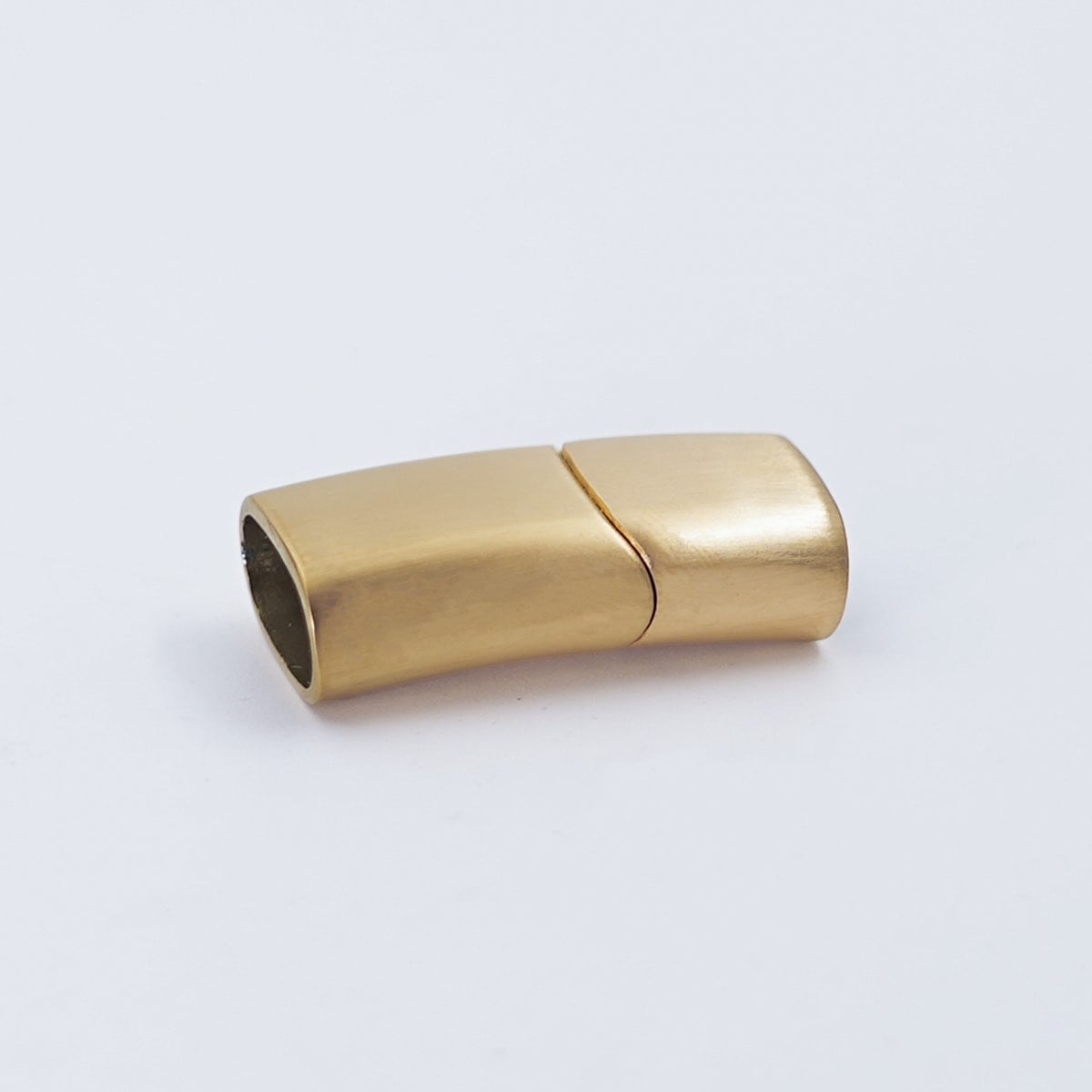
A related published item, the conector elétrico magnético, is also described as a no-prong connector for embedding into devices. Its short details list model RC-ENP1020, a 10 × 2 mm size, a nickel finish, and a packing note that one set is one female. The description also gives a female diameter of 10.5 mm and a thickness of 2 mm, with female capsule options in iron, common brass or environmental brass, and a male capsule in iron. Because the two pages do not present identical dimensions, they should not be merged into one specification. Use the selected product drawing, and confirm whether the enquiry is for a single contact, a mating pair or an assembled unit.
Confirm the assembly conditions before choosing the part
The validation guide treats no-prong, embedded or machined contact concepts as a possible route for rigid housings and embedded assemblies, while textile and flexible assemblies may start with prong or tubular-rivet mounting. That is a selection starting point, not a rule that every plastic housing must use a no-prong snap.
Before a sample is ordered, the brief should record:
- the application and whether a detachable magnetic connection is actually required;
- the housing or substrate, including wall thickness, rear clearance and access for assembly;
- how the part will be retained: embedded moulding or another hidden installation method;
- the intended mating part, rather than a second item chosen only by nominal diameter;
- the current path through the assembly, so that a coating, moulded-over area or cosmetic finish does not interrupt a contact surface that must remain conductive.
The guide is clear that parts with the same nominal diameter should not be assumed to be compatible. Validate the actual mating pair. Platform sizes of 8, 10, 12, 14 and 18 mm are published as starting points, plus custom development, but not every diameter offers every mounting structure.
If wiring or soldering is later added around a no-prong part, that is a separate assembly decision. The validation guide discusses solder joints at tubular rivets, prongs and rear metal areas, and asks teams to agree the soldering method, joint location and sample acceptance criteria before production. Do not copy process settings from a different snap. For a no-prong, embedded part, first confirm whether a rear termination is even part of the selected drawing.
Agree a project-specific sampling plan
Electrical performance should be validated against the application on samples. The published guide asks for current, voltage and contact-resistance targets from the project; it does not prescribe a universal rating. Relevant available reports can be supplied on request, but a report for one sample or a shared plating process does not certify every finished assembly.
A practical sample plan can include the following checks, with the setup and acceptance criteria agreed for the project:
- Confirm the selected drawing: no-prong mounting, contact geometry, dimensions and whether a mating part is included.
- Record the housing or substrate, the installation method, and any mould or embedding conditions that will be used in production.
- Map the intended current path and mark interfaces that must remain free of coating or over-moulded material.
- Verify fit and alignment in the actual housing, including rear clearance and the visible or contact face after embedding.
- Validate the actual mating pair, including gap, alignment and magnetic engagement in the intended arrangement.
- Agree any contact-resistance, magnetic-pull, corrosion or cycling checks, including the measurement method and fixture, rather than borrowing limits from another model.
- If soldering or wiring is in scope, agree the joint location, method and inspection before the sample is built.
- Confirm finish, including any nickel or nickel-free requirement, against evidence that relates to the selected configuration.
- State whether the sample is for design review or for production release, and keep the approved drawing, sample and acceptance criteria together.
Component testing supports development. It does not replace final-device validation.
Keep the brief conservative
Customisation of size, magnetic strength, plating and packaging can be discussed, but those options should follow the mounting and drawing review. Do not treat a plating name as a performance rating, and do not transfer one model’s test result to a different assembly. If the required no-prong configuration is not shown on the selected page, send the drawing, the housing details and the intended mating arrangement for review.
Richarms is a magnetic snaps manufacturer and custom bag hardware factory founded in Foshan, China, in 2003.


 Portuguese
 English
 French
 Italian
 Spanish
 Turkish
 Korean
 Japanese
 German
 Dutch