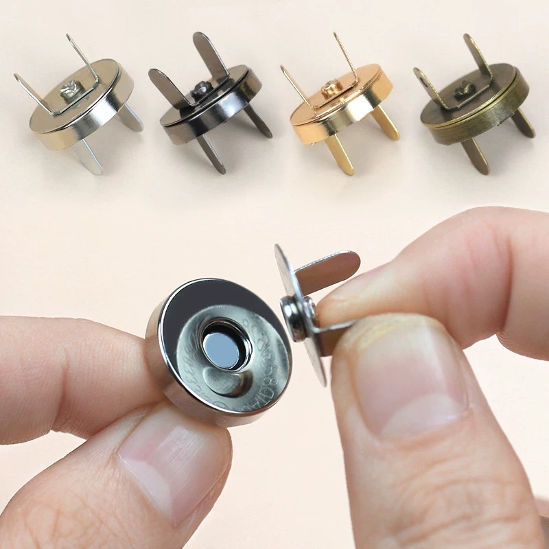
Electrode magnetic snap mounting connects the selected contact interface to the rest of the product. The front mating geometry and the rear attachment need separate checks: a compatible pair can still be unsuitable if its terminal, stem or backing does not fit the assembly.
Begin with a section view of the installed component. Show the counterpart, supporting material, electrical termination and available enclosure space. This helps the supplier evaluate the interface you need rather than selecting from a photograph alone.
Define electrode magnetic snap mounting dimensions
A nominal diameter is a useful identifier, but it leaves many fit questions unanswered. Mark the contact-face diameter, mating depth, installed height and rear projection. Where a stem or tab is used, show its diameter or width, length, spacing and relationship to the main body.
Identify the drawing datum and which tolerances affect mating or assembly. A cavity, washer, insulation layer or folded terminal can change the final stack height. Specify the installed clearance instead of assuming it equals the loose component's thickness.
Bu conductive magnetic snap connector overview places these dimensions within the wider selection process.
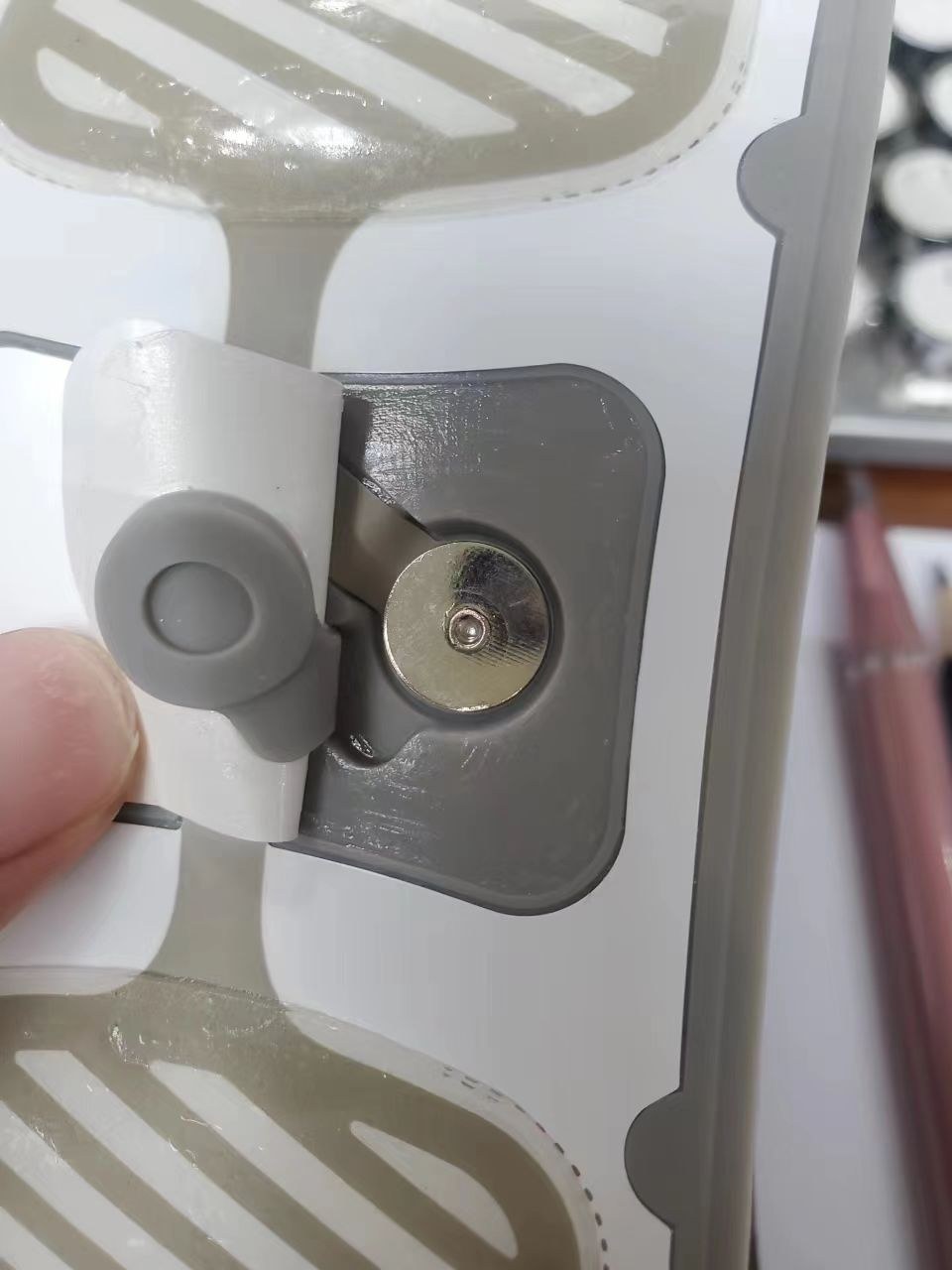
Compare mounting structures by the job they perform
Stem and backing arrangements
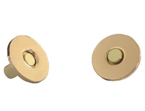
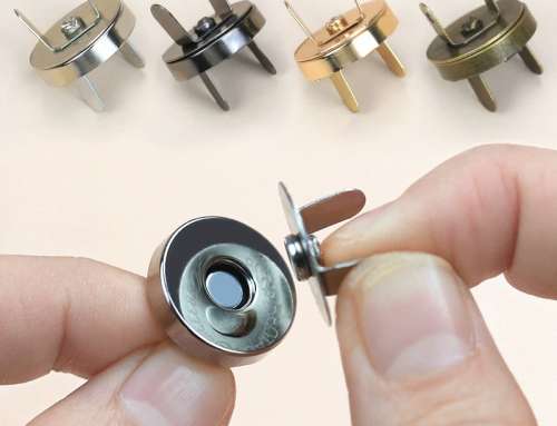
A stem-based structure needs a defined receiving hole and fastening arrangement. Check the supported material thickness, backing surface and the condition of the installed stem. Record whether washers or other matching parts are supplied with the contact.
The assembly process should support the intended surfaces without deforming the mating face. Installation force and tooling belong in the sample review; a similar-looking fastening tool is not proof of compatibility.
Flat or angled terminal arrangements
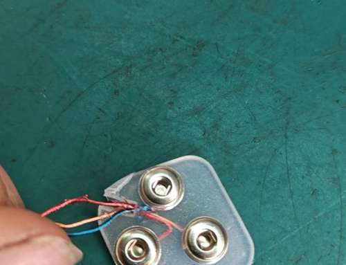
A terminal can constrain board clearance, cable routing and assembly access. Show the board hole or pad position and identify which feature provides mechanical support. Where the terminal is soldered, review its electrical role and the process separately from the mounting function.
Bu solderable connector guide lists the process information needed. Do not infer a qualified soldering cycle from the shape of a prong.
No-prong structures
A flat back may be considered where projecting features conflict with the housing design. The surrounding assembly still needs a defined way to locate and retain the component while leaving the intended contact surface accessible.
Richarms' no-prong conductive magnetic snap listing provides a format to discuss. If embedding or molding is proposed, the project must evaluate the relevant heat, pressure, material flow and retention requirements. Removing a prong does not by itself establish process suitability or eliminate assembly defects.
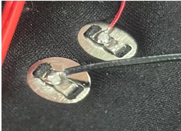
Protect the electrical boundary
Show the intended conductive route and any surfaces that must remain isolated. Do not infer separate electrical channels from a concentric appearance, or assume that a visible ring is an insulating feature. The material specification and section drawing should establish those functions.
If the application includes more than one contact, check alignment and what happens when the mating part is rotated or partially engaged. Have the device team define the relevant requirements and evaluate them in the complete design.
For interface selection, refer to the magnetic, stud-snap and pin comparison.
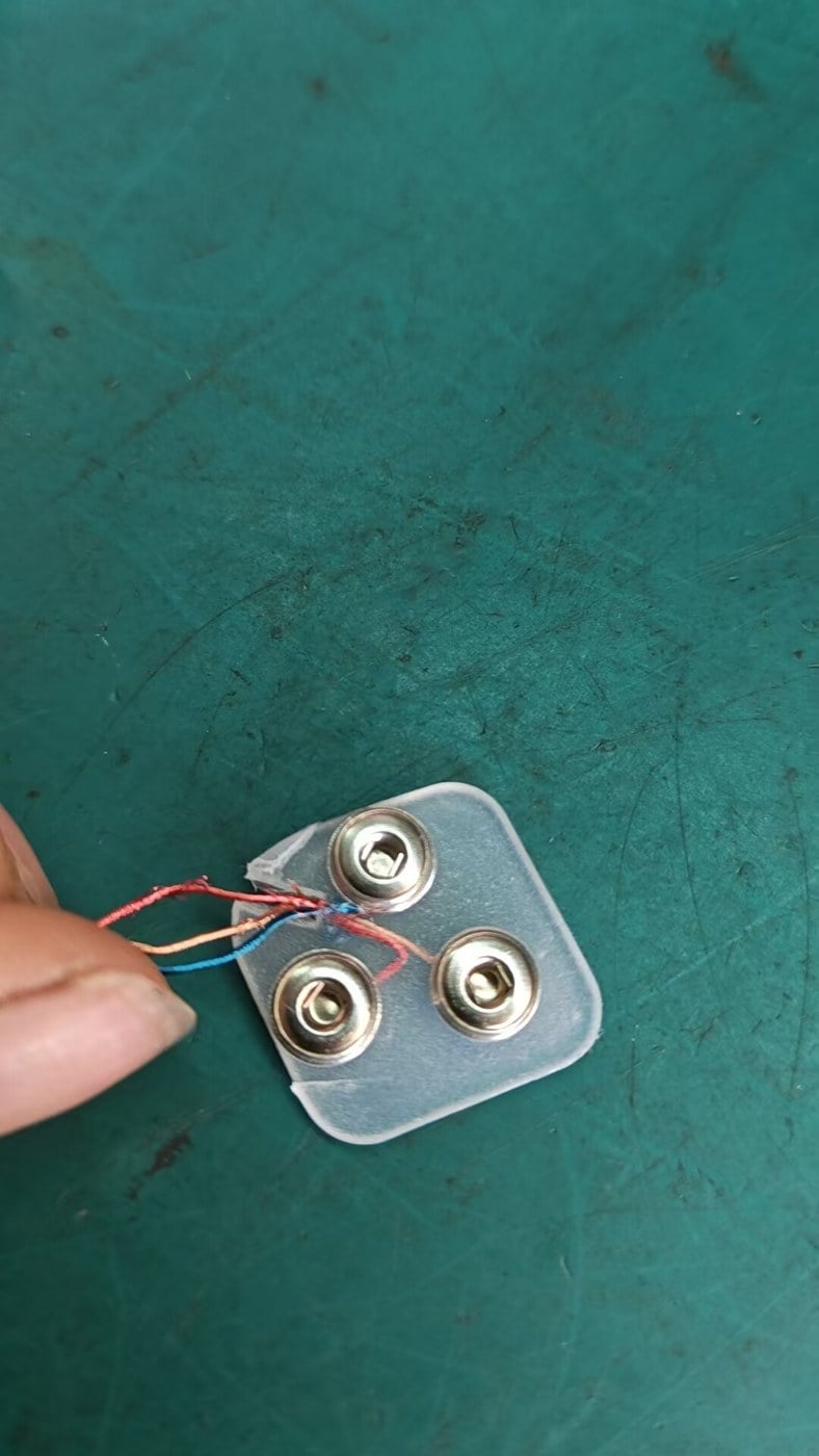
Evaluate the installed sample
Build a sample using the intended support materials and counterpart. Check whether the contact seats fully, stays aligned and remains accessible for the intended release action. Inspect for loose fixing, deformation and unintended pressure on nearby parts.
Apply the project's defined cable or handling loads through the intended load path. Keep electrical continuity checks separate from the visual assessment. A stable-looking attachment is not sufficient evidence of contact reliability.
Record the component revision, mating part, supporting material and assembly method with the results. This turns an approved sample into a useful reference for production and later changes.
Prepare a drawing-based enquiry
Send Richarms the installed section view and counterpart details, together with the proposed assembly process, environment, quantity and timing. If an existing structure is close but one feature prevents integration, identify that feature explicitly. The custom conductive magnetic snap guide explains how to turn it into a controlled development request.


 Turkish
 English
 French
 Italian
 Portuguese
 Spanish
 Korean
 Japanese
 German
 Dutch