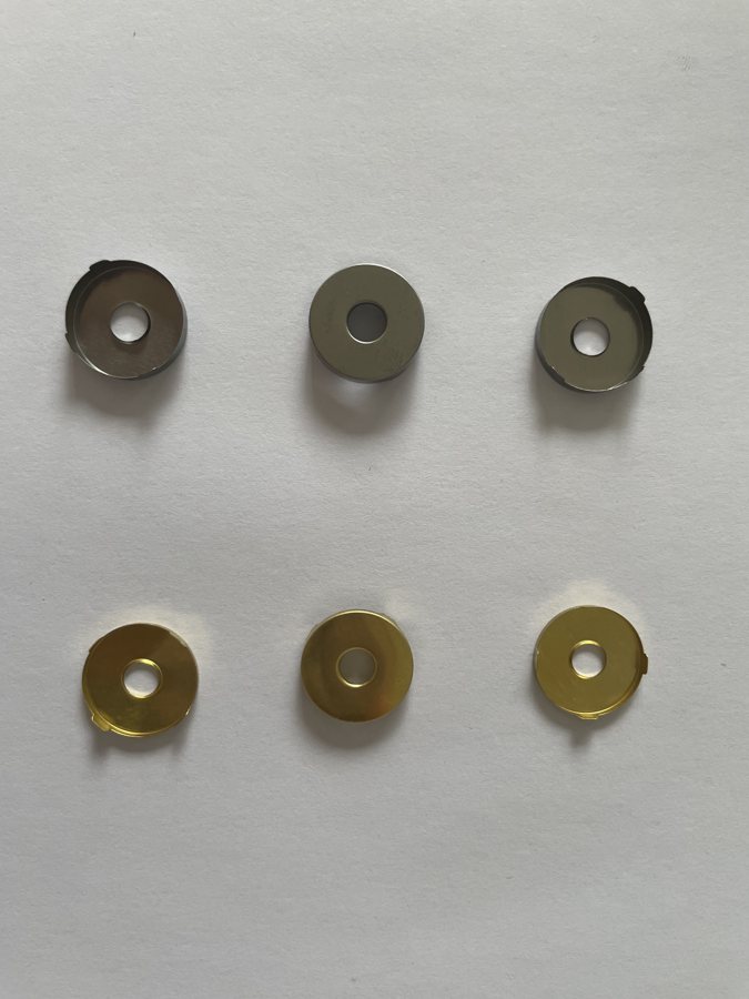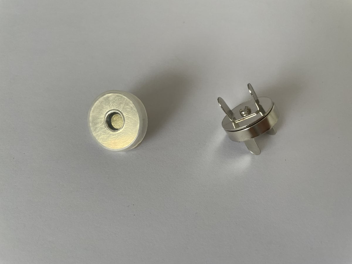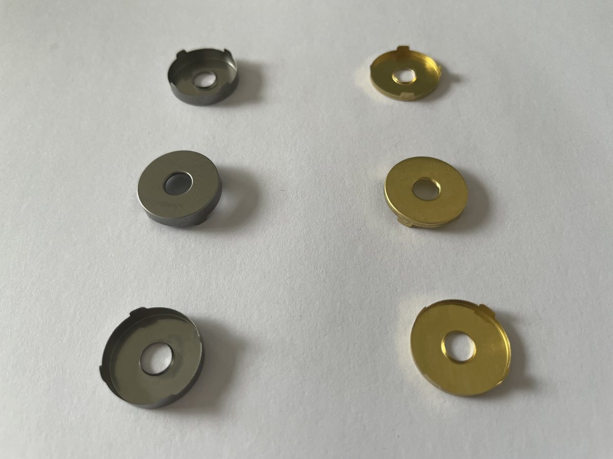
Electrode connector contact reliability should be assessed within a clearly defined test boundary. A changing reading or interruption may involve the mating contact, cable termination, board connection or another part of the assembly. Testing is most useful when it helps distinguish these possibilities instead of assigning every symptom to the magnet or snap.
This guide is a planning framework for engineering teams. Test conditions and acceptance criteria must be defined for the project; it does not supply a universal resistance limit, cycle-life rating or medical-device validation protocol.
Define electrode connector contact reliability requirements
State what must remain connected, under which operating conditions and for which intended service period. Identify the failure observations that matter, such as an interruption during movement, a change in measured resistance or damage to the fixing.
Draw the measurement boundary. A result measured across a complete cable assembly includes a different set of components from a result measured across the mating interface. Name the boundary in the test report so the two results are not treated as interchangeable.
Use the conductive magnetic snap connector guide to connect the test brief with component and assembly selection.
Establish a repeatable baseline
Identify the sample lot, component revision, counterpart and assembly condition. Record the instrument, current or measurement mode, sensing locations, fixture and environmental conditions used for the baseline.
Four-terminal measurement can reduce the influence of measurement leads and probe contacts when measuring small resistances. HIOKI explains the method in its low-resistance measurement guide. Position the sensing points to match the boundary being evaluated: the method does not remove the resistance of the connector interface that you intend to measure.
Check the instrument instructions and measurement setup with the responsible engineer. A continuity indication can be useful for finding an open path, but it is not a substitute for a defined low-resistance measurement or an interruption-monitoring method.
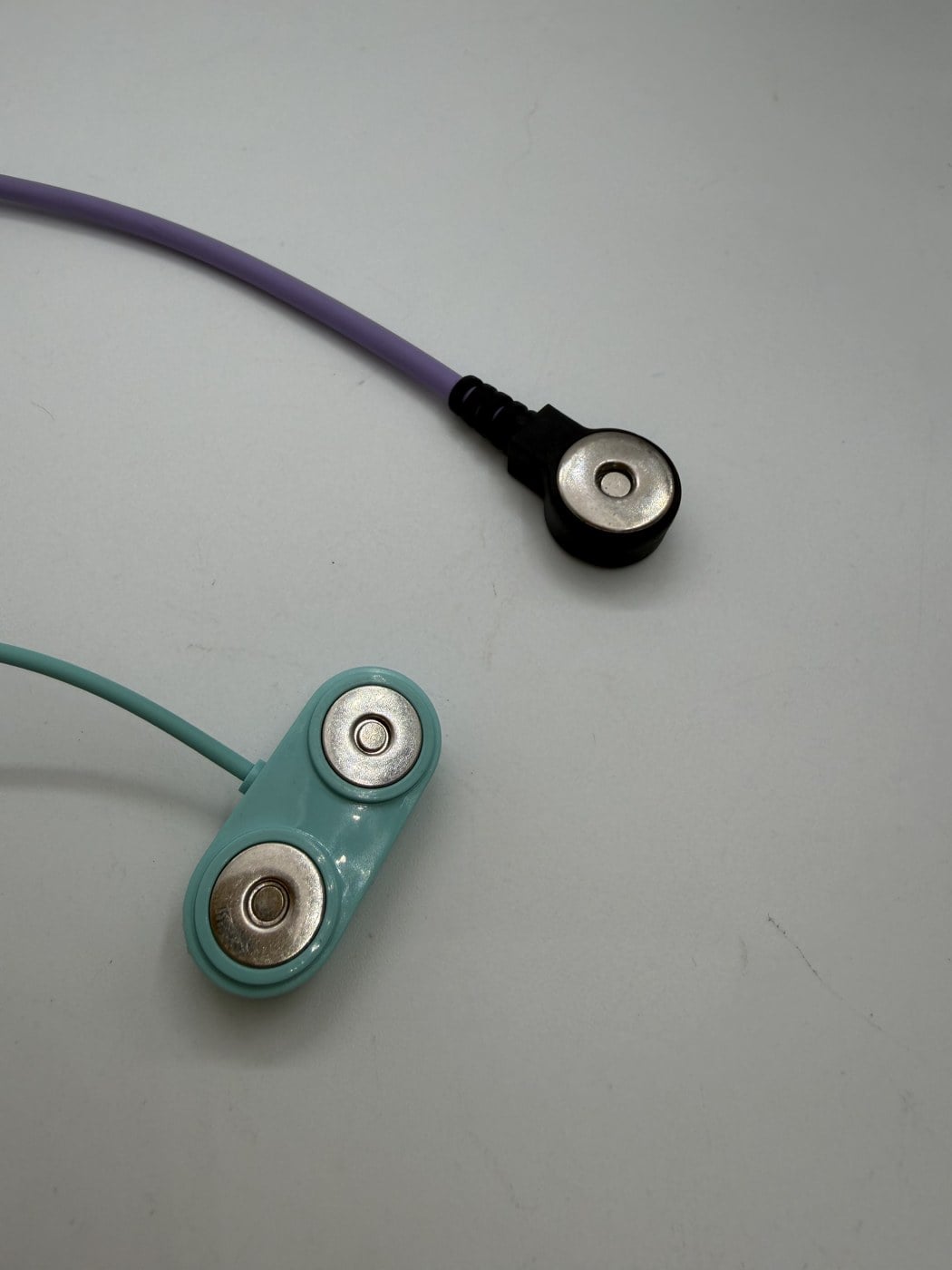
Evaluate movement without losing the cause
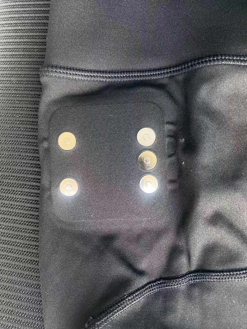
Use a fixture that represents the intended mounting and cable support. Define the movement direction, displacement, loading and duration. Record whether the connector remains fully seated and whether movement occurs at the termination or fixing.
A static reading taken after movement may miss a short interruption. If brief interruptions matter to the design, specify monitoring that can capture them and record the relevant timing. Establish the method before comparing two connector versions.
Bu mounting guide helps identify differences in support and load paths that could otherwise distort the comparison.
Review assembly and exposure separately
A practical test plan can separate the as-received pair, the assembled sample and samples after defined exposure. That makes it easier to identify when a change first appears.
| Stage | Information to keep with the result |
|---|---|
| Initial sample | Part revision, counterpart, lot and baseline condition |
| After assembly | Joining or fastening process, fixture and inspection record |
| During movement | Motion and load conditions, monitoring method and observed interruptions |
| After exposure | Exposure method, duration, recovery or drying condition and visible changes |
| After repeated mating | Cycle definition, count, operating action and inspection intervals |
Define exposure around the intended use, including relevant moisture, cleaning or storage conditions. A generic finish name does not establish corrosion resistance in every environment. Passing one exposure test does not automatically establish performance in another.
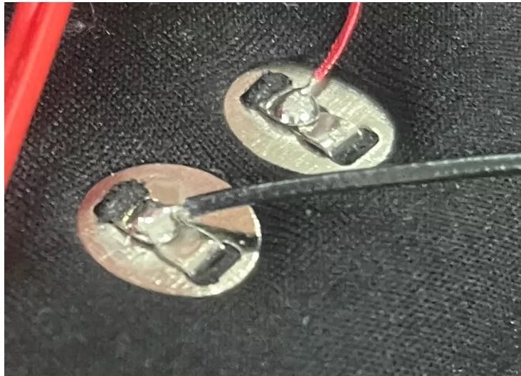
For soldered assemblies, refer to the solderable magnetic snap connector checks. Keep any measured process-related change tied to the specific sample and test conditions.
Distinguish observations from explanations
“Resistance increased after assembly” is an observation when supported by a controlled measurement. “The magnet caused the increase” is a proposed explanation that needs further evidence. Recheck the test arrangement and examine other interfaces before changing the design.
Similarly, electrode adhesion, stimulation sensation and connector continuity are different observations. Connector testing cannot establish a clinical effect or show that replacing the contact will resolve an unexplained device complaint.
Agree on acceptance before the test
Define pass/fail criteria, sample selection and how anomalies will be handled before approving production. Preserve both the results and the conditions that produced them. If a changed contact or mounting structure is needed, use the custom development workflow to connect that change with a new sample revision.
Share the interface drawing and proposed validation requirements with Richarms. Confirm which checks can be supplied with the component and which remain part of the customer's assembly or device evaluation.


 Turkish
 English
 French
 Italian
 Portuguese
 Spanish
 Korean
 Japanese
 German
 Dutch