Magnetic snap installation problems can involve the attachment, the material or the way the closure meets. Start by describing what moves or looks wrong. A snap that turns in its panel is a different problem from a securely attached snap whose mating faces do not line up.
The checks below are a diagnostic route, not a claim that one symptom has one guaranteed cause. Keep the affected samples and compare them with an approved assembly before changing the setup.
Classify magnetic snap installation problems first
| Observed symptom | First checks | ||||
|---|---|---|---|---|---|
| Hardware moves in the material | Component completeness, backing, fixing stack, preparation and formed attachment. | ||||
| Cap or fixing end is deformed | Die identity, support profile, component seating and approved setting conditions. | ||||
| Material is marked or damaged | Hole or slot preparation, support, local stack and contact with the tooling. | ||||
These are possible areas to investigate. Do not infer a confirmed root cause from a single front photograph.
Inspect both sides of the assembly
Photograph the front, back and side of the affected area. Include both mating halves and one loose complete set. Note whether the problem appears immediately after setting or after a later assembly step, such as lining or stitching.
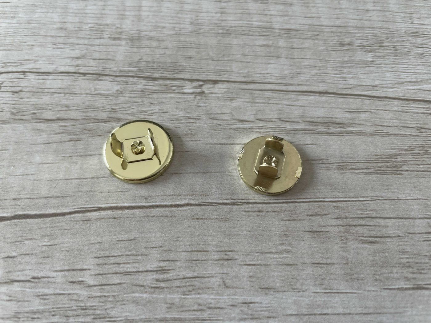
Check the required backing parts against the selected model. Inspect the actual fixing end, not only the decorative face. If a component has been substituted, record that change rather than assuming it is equivalent.
For riveted models, review the length and material-stack checklist. For weak closure with secure fixing, use the separate magnetic strength guide.
Review preparation and positioning
Compare hole or slot positions with the approved sample and component drawing. Check whether the two panels were marked in the intended orientation. Test alignment in the final product shape, because a fold or seam can affect how the magnetic faces meet.
Keep a record of the preparation tool as well as the setting die. A change to the cutting operation can alter the assembly even when the final press setup stays the same. Do not enlarge holes or slots on finished goods without an approved correction method.
Confirm the die pair and support
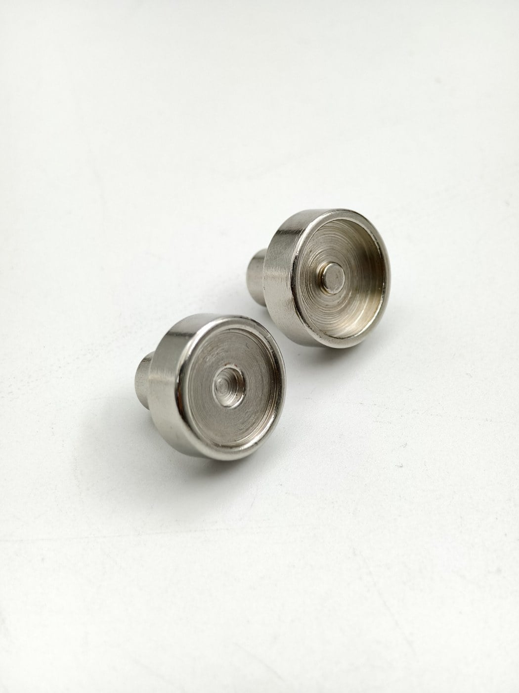
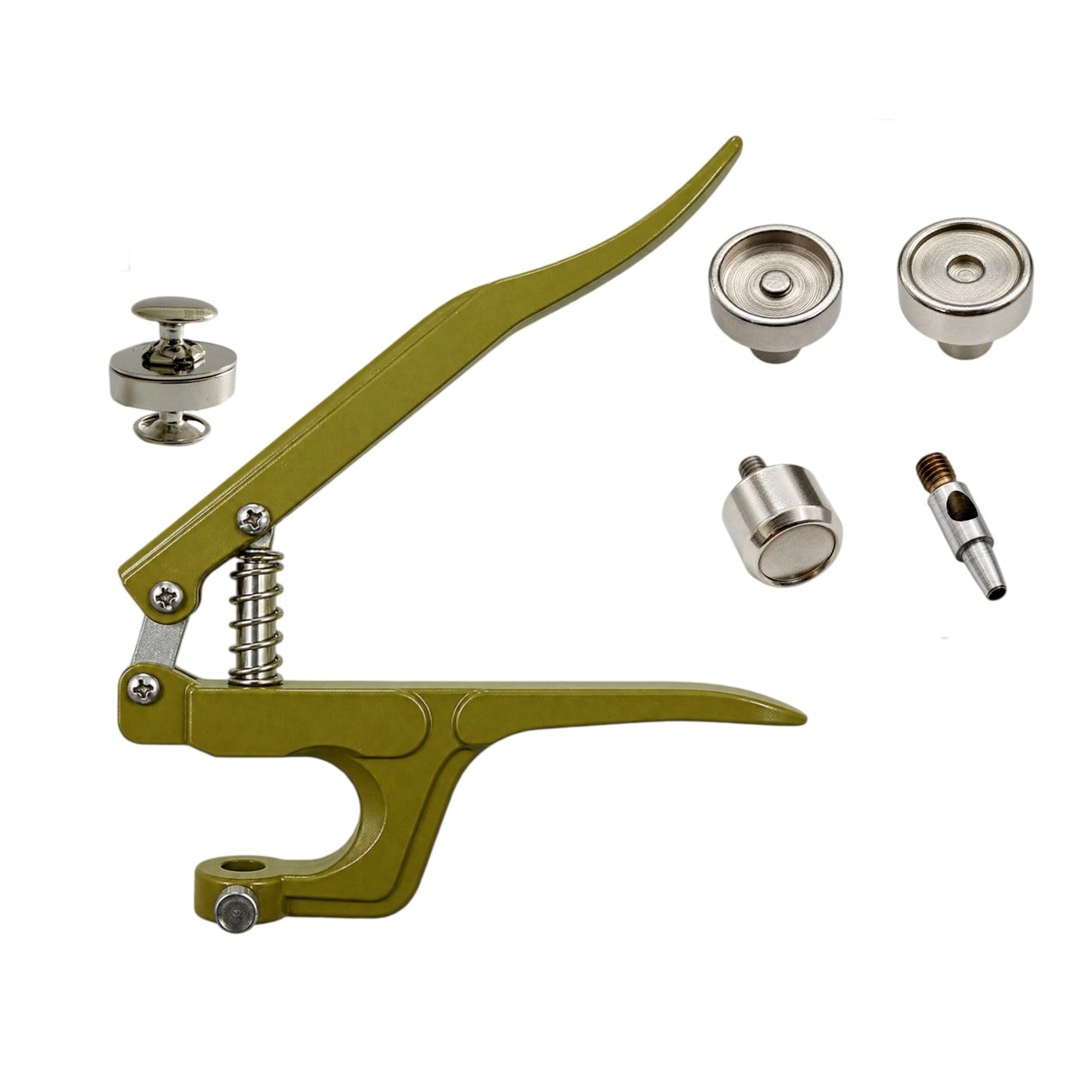
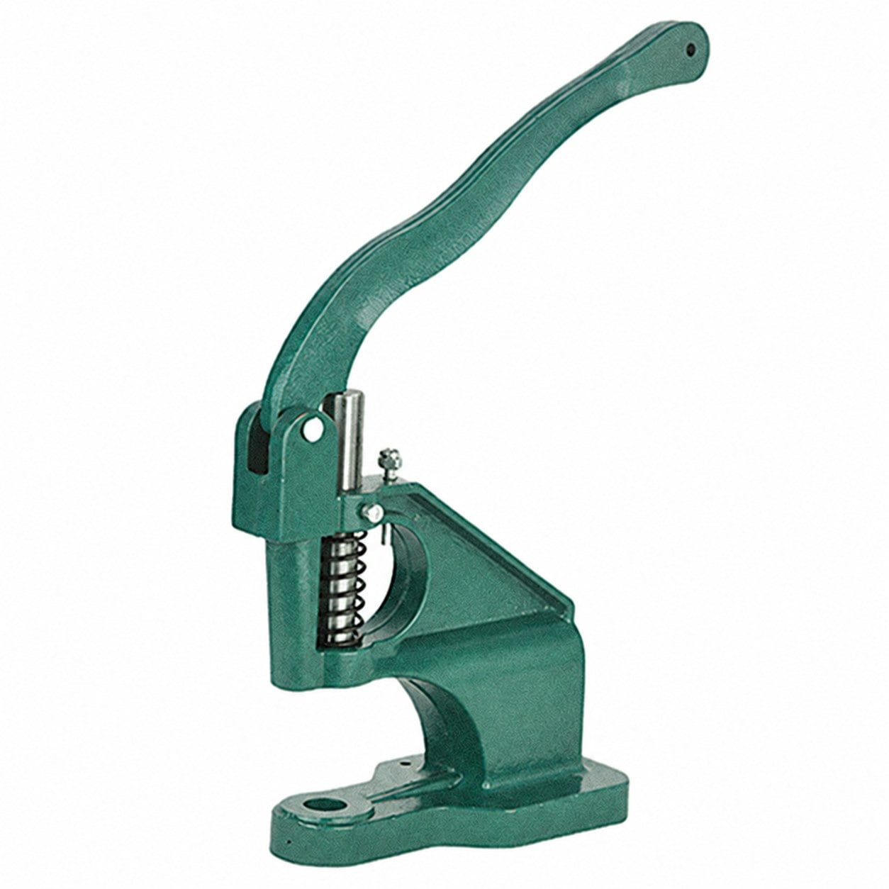
Identify both dies and inspect their working faces. Confirm that they belong to the snap model and tool system. Look for incorrect seating, contamination or visible damage, and have the tooling supplier assess concerns before continued use.
Read the setting die compatibility guide if the equipment or tooling came from another supplier. A mount that fits does not establish that the working face supports the cap or forms the fixing end correctly.
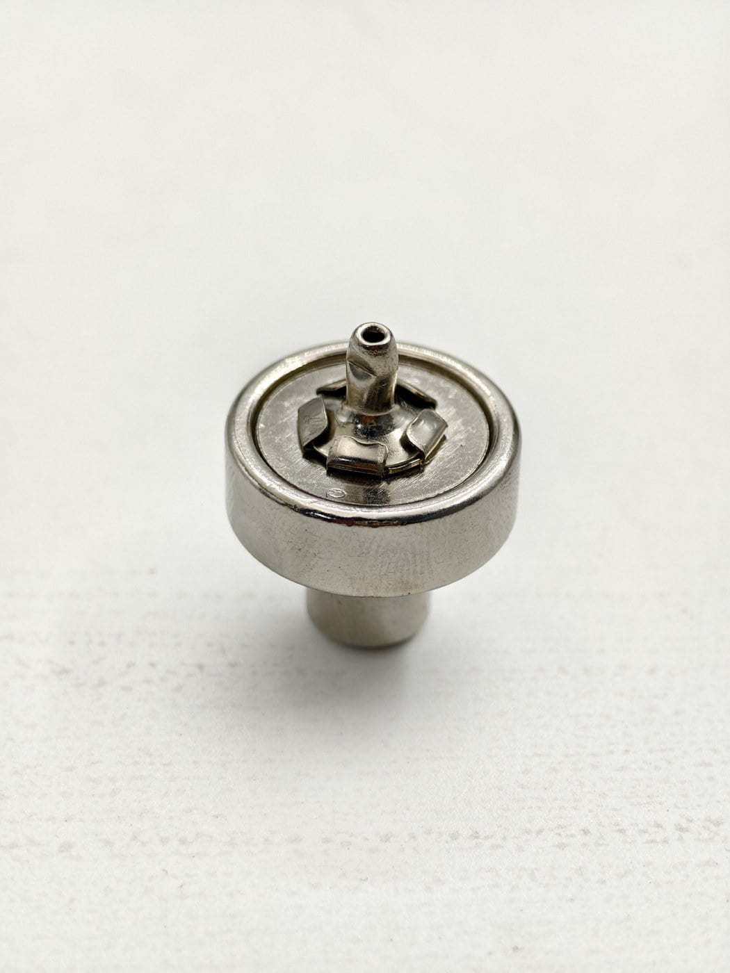
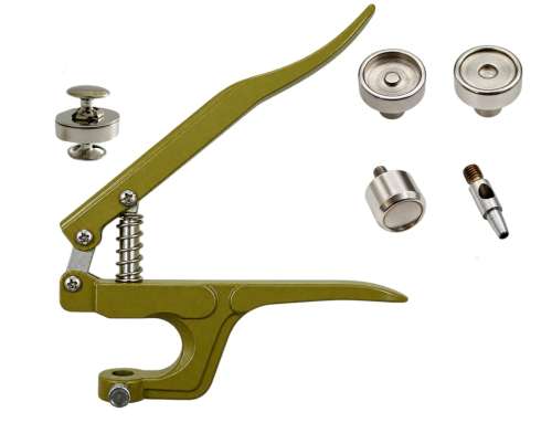
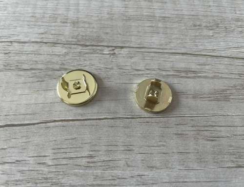
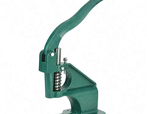
The reference photos show components and tooling to inspect; they are not before-and-after evidence of a corrected failure.
Illustrated installation references
Use these model-specific examples to review the assembly sequence. Match the snap, preparation tool and setting tools before applying either method to your material.
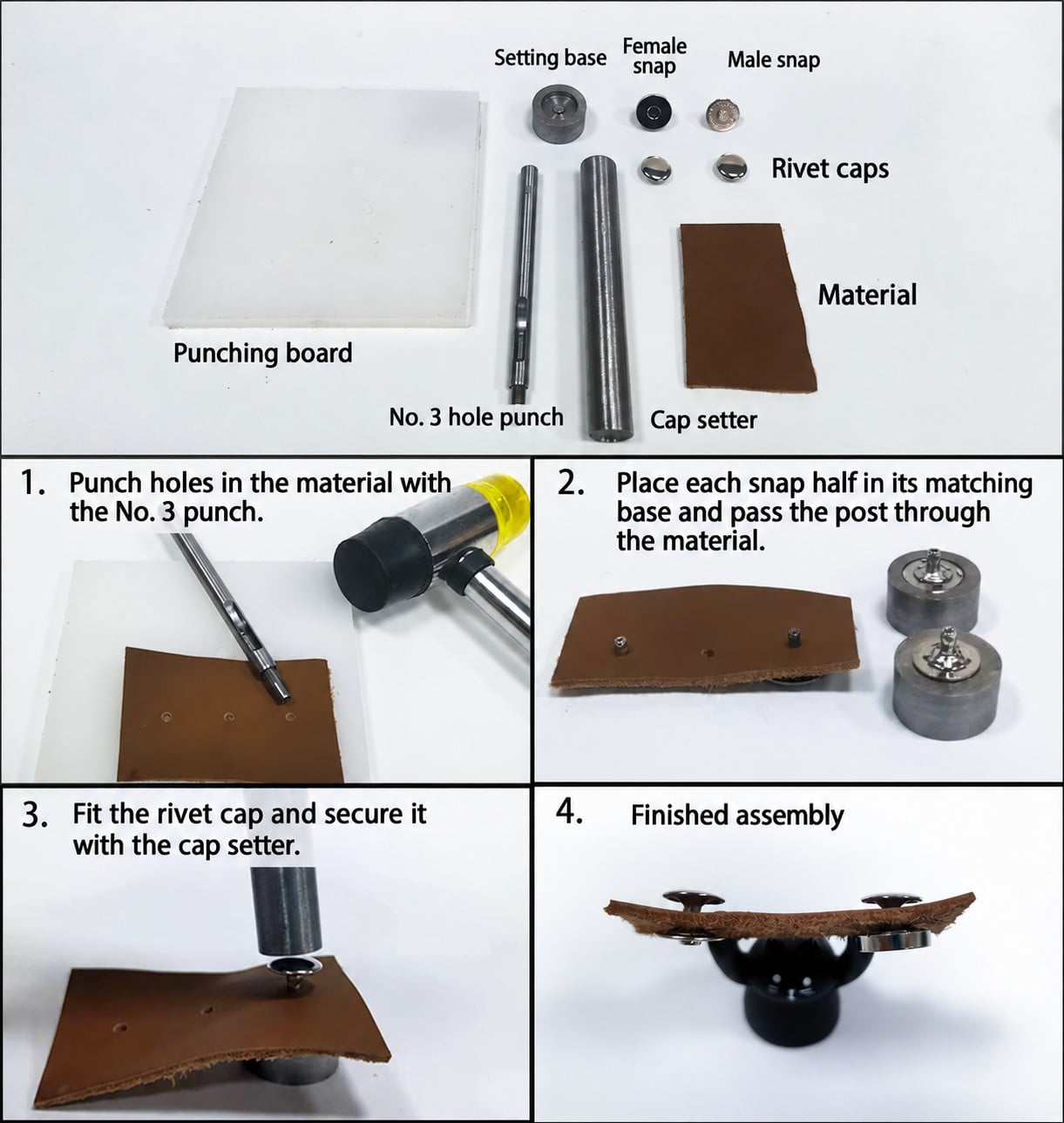
Rivet magnetic snap: support the snap before setting the cap
Check the matching base, the post passing through the material and the cap setter shown in the sequence. The No. 3 punch label identifies the illustrated tool; confirm the required hole size for your selected model.
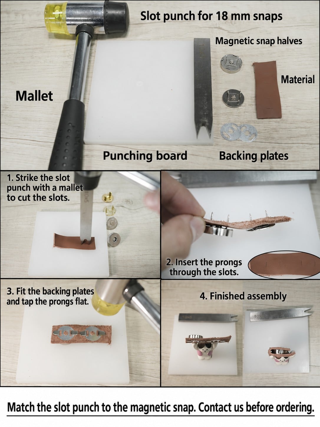
Prong magnetic snap: match the slots and backing plates
Check slot spacing against the actual prongs, then confirm the backing plates are fitted before the prongs are formed. The illustrated punch is labeled for 18 mm snaps; this does not mean an 18 mm slot width or universal compatibility.
Test a controlled correction
Set aside affected output and run the proposed correction on sample material. Change one identified factor at a time, keeping the other components and conditions recorded. Compare the result with the approved sample and the buyer’s acceptance requirements.
Do not automatically increase pressure, repeat hammer strikes or re-press a finished item. Those actions can obscure the original problem or further deform the assembly. Ask the supplier whether the affected hardware can be reworked or should be replaced.
Send useful evidence for troubleshooting
- Snap model, order reference and a complete loose-set photo.
- Front, back and side photos of the installed result.
- Material layers, backing parts and thickness information.
- Tool model, both die identifiers and current approved setup details.
- When the symptom appears and which recent changes were made.
Send this information to Richarms for review. Once the correction is approved, update the setup record and retain a new reference sample. The installation guide provides the full sequence for approving a fresh combination.

 English
 French
 Italian
 Portuguese
 Spanish
 Turkish
 Korean
 Japanese
 German
 Dutch